Barrel-type friction-changing damper

A variable friction and damper technology, applied in the direction of friction shock absorbers, etc., can solve the problems of high cost, fixed maximum value, difficulty in meeting large tonnage and large deformation capacity at the same time, and achieve the goal of improving output tonnage and large displacement capacity Effect

Inactive Publication Date: 2008-07-09
BEIJING UNIV OF TECH
View PDF0 Cites 24 Cited by
  • Summary
  • Abstract
  • Description
  • Claims
  • Application Information

AI Technical Summary

Problems solved by technology

[0008] 1) Although the pseudo-viscous damper can produce a hysteretic curve similar to that of the viscous damper, its maximum value is still fixed, which is the main difference from the viscous damper, so the damper still has conventional frictional damping The device cannot adapt to the defect of strong vibration and weak vibration at the same time;
[0009] 2) Although the performance of the semi-active friction device is superior, the structure of this type of device is complex, the cost is high, and the maintenance requirements are high, so it is currently impossible to popularize it;
[0010] 3) The centripetal friction damper has an exquisite structure, but since the positive pressure on the friction surface mainly comes from the spring in the middle, as shown in Figure 1.(c), in orde

Method used


Image

  • Barrel-type friction-changing damper
  • Barrel-type friction-changing damper
  • Barrel-type friction-changing damper

Examples


Embodiment 1

[0042] In this example, Teflon (Teflon) coating is used as the inner wall contact surface of the second friction sleeve 17 .

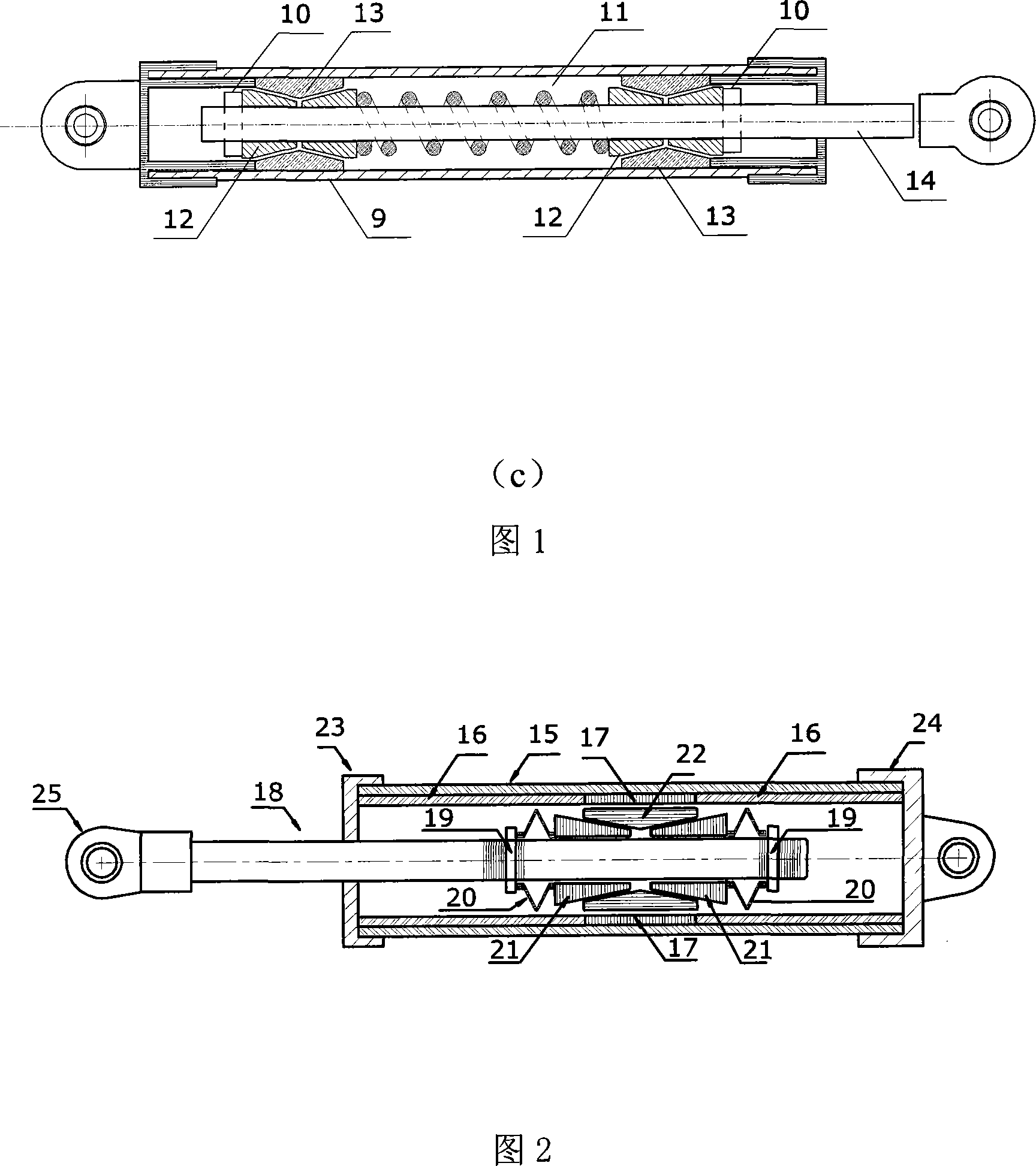
[0043] As shown in FIG. 11 , two first friction sleeves 16 are connected to two ends of a second friction sleeve 17 respectively, and the outer sleeve 15 is sleeved on the outer walls of the above three friction sleeves. The outer diameters of the first friction sleeve 16 and the second friction sleeve 17 are the same, which are both equal to the inner diameter of the outer sleeve 1 . The part where the second friction sleeve 17 contacts the friction slider 22 is located on the same cylindrical surface as the inner wall of the first friction sleeve 16 . The friction coefficient of the contact surface between the inner wall of the second friction sleeve 17 and the friction slider 22 is smaller than the friction coefficient of the contact surface between the inner wall of the first friction sleeve 16 and the friction slider 22 . In this embodiment, the ...

Embodiment 2

[0049] As shown in FIG. 10 , balls 30 are embedded in the inner wall of the second friction sleeve 17 in this embodiment, and other components are the same as those in Embodiment 1.

[0050] The width of the friction surface of the friction slider 22 is equal to the height h of the second friction sleeve 17 , as shown in FIG. 11 . The contact position between the ball 30 in the second friction sleeve 17 and the friction slider 22 is located on the same cylindrical surface as the inner wall of the first friction sleeve 16 . The rolling friction coefficient of the contact surface between the friction slider 22 and the second friction sleeve 17 is less than 0.01 times of the friction coefficient of the contact surface between the friction slider 22 and the first friction sleeve 16 .

[0051] Initially, the friction slider 22 is aligned with the second friction sleeve 17, as shown in FIG. 11 . When the damper is deformed, the contact area between the friction slider 22 and the co...

Embodiment 3

[0053] As shown in FIG. 13 , the width of the friction surface of the friction slider 22 in this embodiment is greater than the height h of the second friction sleeve 17 . All the other parts are the same as in Example 2.

[0054] Initially, the friction slide 22 is aligned with the second friction sleeve 17 . Since the width of the friction slider 22 is greater than the height h of the second friction sleeve 17, when the friction slider 22 moves from the initial position relative to the second friction sleeve 17, the friction resistance of the damper will remain unchanged until the friction One end of the slider 22 enters the range of the second friction sleeve 17, as shown in FIG. 15 , after that, the frictional resistance of the damper will increase linearly as the relative displacement continues to increase. Therefore, the hysteresis curve of Example 3 will be as shown in FIG. 16 .

[0055] The application form of the cylindrical friction damper proposed in this embodime...


PUM


Abstract

The invention relates to a cylinder-type variable friction damper, and can be used for building structure damping control and locomotive damping. The invention comprises an outer sleeve, a first friction sleeve, a second friction sleeve, a sliding axle, a disk spring, a locknut, an extrusion cone ring and a friction slip. An inner sleeve comprises the second friction sleeve and the first friction sleeves arranged on both ends of the second friction sleeve. The inside diameters of the first friction sleeve and the second friction sleeve are arranged on the same cylindrical surface. A left end plate and a right end plate having a hinge are permanently connected on the left end and the right end of the inner sleeve and the outer sleeve. During the deformation course of the cylinder-type variable friction damper, the area of the contact face which actually provides the frictional resistance varies with the deformation of the damper; the positive pressure on the complete contact face is kept unchanged. In this way, the friction is variable. The damper has the characteristic of linear damping. The capability of dissipation of energy increases with the increase of the deformation amplitude. When the invention is used for damping control of building structures, the invention can meet the requirement for damping under strong vibration and weak vibration, and has high practical application value.

Description

technical field [0001] The invention relates to a cylinder type variable friction damper, which can be applied to vibration reduction control of building structures and vibration reduction of locomotives. It can also be used to make dampers used in aerospace, electronics, chemical industry, energy, instrumentation, medical treatment, sanitation and other fields. Background technique [0002] The friction damper is a kind of control device that uses the frictional energy dissipation of the friction surface to dissipate the vibration energy. Friction surfaces for friction dampers in construction typically include steel-bronze, steel-steel, and heavy-duty brake linings. The core part of a common friction damper is one or more pairs of friction surfaces with a certain preload. The external force needs to overcome the friction between the friction surfaces to drive the relative motion of the friction surfaces of the damper. The preload and the properties of the friction surface...

Claims


Application Information

Patent Timeline
IPC IPC(8): F16F7/09
Inventor 周锡元彭凌云闫维明
Owner BEIJING UNIV OF TECH
Why Eureka
Try Eureka