
Optical waveguides ring-shaped resonant cavity elementary structure parameter test device and its method

A ring-shaped resonant cavity and basic structure technology, which is applied in the testing of machine/structural components, measuring devices, optical waveguides and light guides, etc., can solve the problems of poor repeatability, low calculation accuracy, and complex testing devices, and improve the limit sensitivity. , the effect of low calculation accuracy, important scientific significance and application value

Inactive Publication Date: 2008-07-09
ZHEJIANG UNIV
View PDF0 Cites 13 Cited by
  • Summary
  • Abstract
  • Description
  • Claims
  • Application Information

AI Technical Summary

Problems solved by technology

[0003] In some previous methods and devices that use the resonance curve of the test ring resonator to obtain the basic structural parameters of the ring resonator, these three basic structural parameters: coupler coupling coefficient, coupler additional loss and waveguide transmission loss are not fully integrated. It is calculated independently, and the other two parameters are generally obtained by testing the resonance curve of the ring cavity based on known or testing any one of the parameters separately. These test devices are complicated, the calculation accuracy is low, and the repeatability is poor.

Method used


Image

  • Optical waveguides ring-shaped resonant cavity elementary structure parameter test device and its method
  • Optical waveguides ring-shaped resonant cavity elementary structure parameter test device and its method
  • Optical waveguides ring-shaped resonant cavity elementary structure parameter test device and its method

Examples


Embodiment Construction

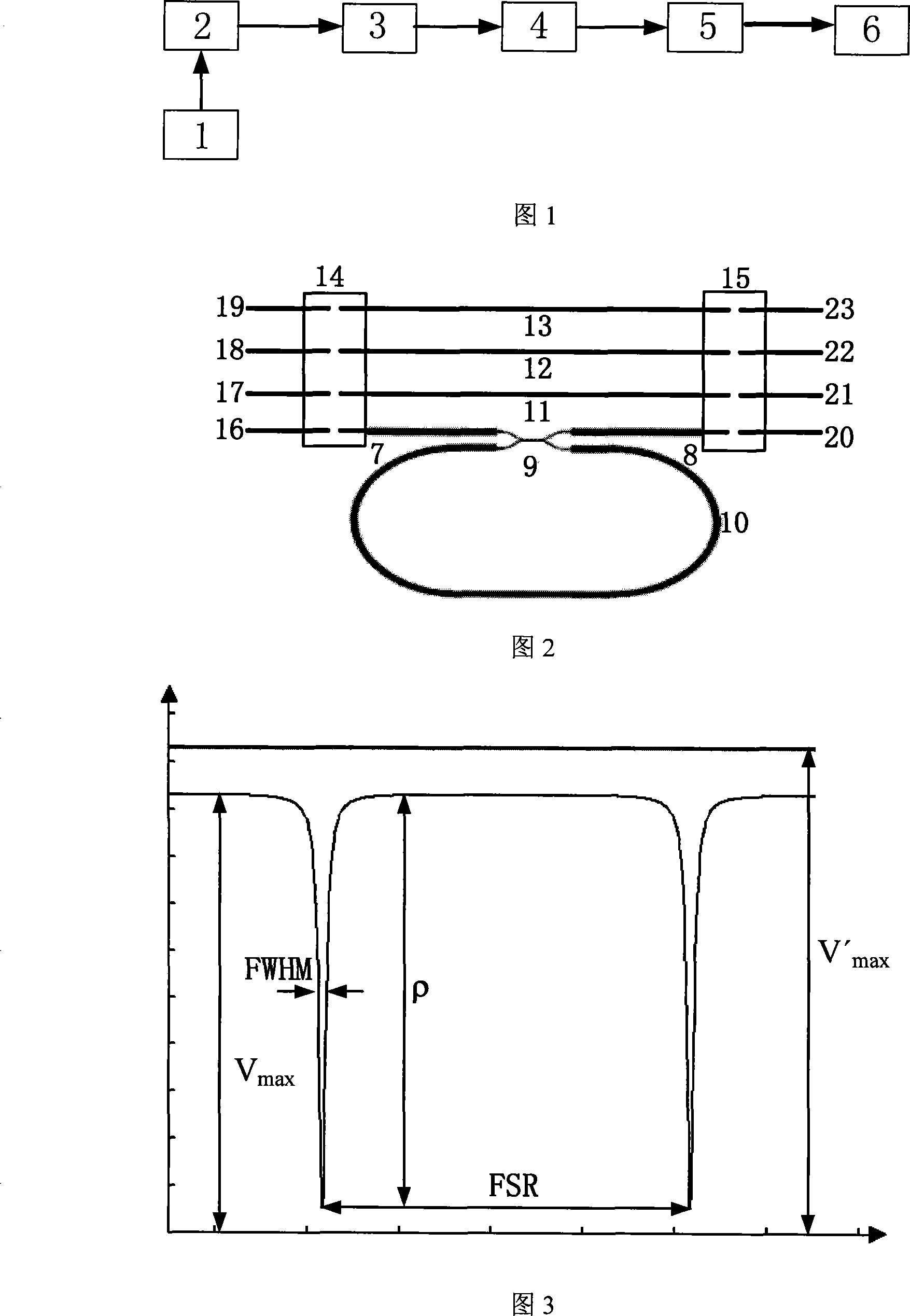
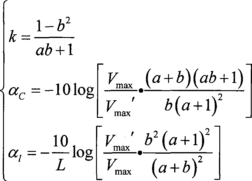
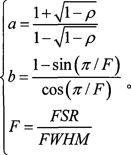
[0022] In the present invention, by testing the resonance curve of the optical waveguide ring cavity and the average output amplitude of three reference straight waveguides, the three basic structural parameters of the optical waveguide ring resonator, including coupler coupling coefficient and additional loss, and waveguide transmission loss are completely independent Calculated. The main reason for using three reference straight waveguides is to use the alignment characteristics of the ribbon fiber to reduce the test error and improve the accuracy of the basic structural parameters of the test optical waveguide ring resonator. According to the three parameters obtained from the resonance curve output by the light wave after the transmission of the ring resonator: the definition of the resonance depth ρ, the free spectral line width FSR of the resonator and the full width at half maximum FWHM of the resonator spectral line, the optical waveguide ring is obtained by using the m...


PUM


Abstract

The invention discloses a device for testing basic structural parameters of an annular resonant cavity of an optical waveguide and a method thereof. The method comprises the following steps of: designing three reference straight waveguides with identical structure on an annular resonant cavity chip of the optical waveguide, coupling by an optical fiber coupler and testing the resonance curve of the annular cavity and the average output amplitude of the reference straight waveguides to obtain the specific values of all structural parameters of the annular resonant cavity of the optical waveguide, including coupling coefficient and additional loss of the coupler as well as transmission loss of the waveguides. The device for acquiring structural parameters of the annular resonant cavity of the optical waveguide comprises a sawtooth wave signal generator, which is sequentially connected with a laser, an annular resonant cavity chip of the optical waveguide, a PD detector, an oscilloscope and a computer. The invention can nondestructively, easily and directly acquire three basic structural parameters of the annular resonant cavity of the optical waveguide, which provides instruction for further designing high-performance resonant cavity of optical waveguide. Meanwhile, the invention has important scientific meanings and application values in improving limit sensitivity and performance of resonant micro-optical gyroscope.

Description

technical field [0001] The invention relates to a testing device and method for basic structural parameters of an optical waveguide ring resonant cavity. Background technique [0002] The optical waveguide ring resonator is the core sensitive part of the resonant micro optical gyroscope, and the most basic ring resonator structure is formed by directly connecting one output port of a directional coupler with an input port. In ring resonators, clarity is often used to measure its performance index, which is defined as the ratio of the interval between two adjacent resonant frequencies to the half-height width of resonant cavity spectral lines. The clarity is determined by the basic structural parameters of the ring resonator, including the coupler coupling coefficient and additional loss and waveguide transmission loss. [0003] In some previous methods and devices that use the resonance curve of the test ring resonator to obtain the basic structural parameters of the ring r...

Claims


Application Information

Patent Timeline
IPC IPC(8): G01M11/00G01M11/02G02B6/10
Inventor 马慧莲王世军金仲和
Owner ZHEJIANG UNIV
Learn More