Laser radar emission and receiving light path parallel regulating system and method

A laser radar and adjustment system technology, applied in the direction of radio wave measurement systems, instruments, etc., can solve the problems of poor accuracy, high cost, complex optical and mechanical structure design, etc., and achieve the effect of accurate judgment

Inactive Publication Date: 2008-07-09
ANHUI INST OF OPTICS & FINE MECHANICS - CHINESE ACAD OF SCI
View PDF0 Cites 29 Cited by
  • Summary
  • Abstract
  • Description
  • Claims
  • Application Information

AI Technical Summary

Problems solved by technology

[0003] The current optical path adjustment can be adjusted according to the strength of the echo signal of the laser radar. This method must be operated by experienced staff, which is highly subjective and has poor accuracy. In addition, the optical path can be adjusted by automatic scanning. This method is relatively complicated in terms of optical and mechanical structure design, and the cost is expensive; it can also be used to launch a laser light source self-collimation system, that is, a level, which is only suitable for long-distance, and the accuracy is not very high

Method used


Image

  • Laser radar emission and receiving light path parallel regulating system and method

Examples


Embodiment Construction

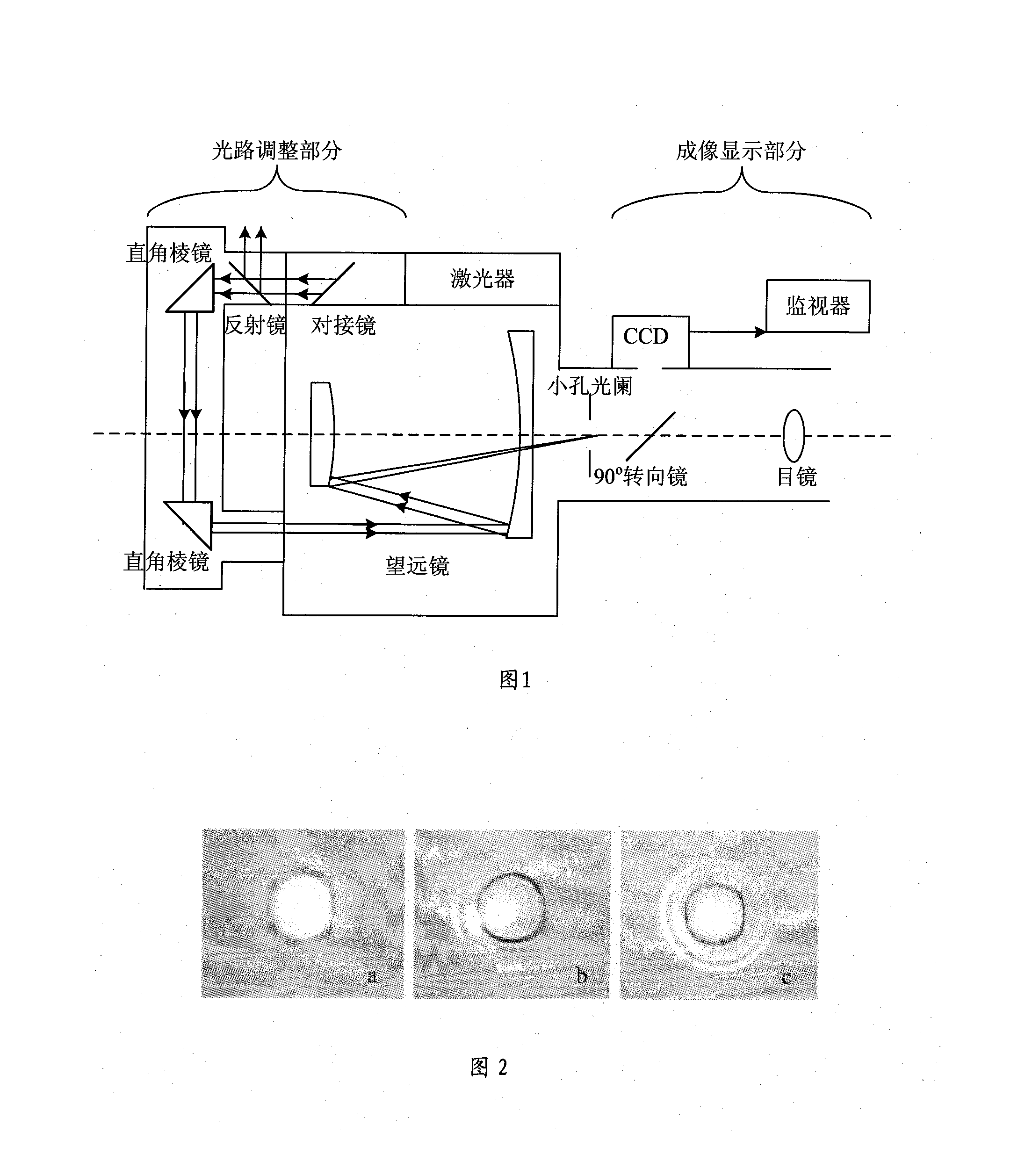
[0018] The laser radar transmitting and receiving optical path parallel adjustment system includes a receiving telescope. A laser whose emitting light direction is parallel to the direction of the optical axis of the telescope is fixedly installed on the receiving telescope barrel, and a butting mirror, a reflector, and a receiver are installed in the optical path in front of the laser. A corner reflector composed of a pair of right-angle prisms is installed in front of the telescope lens barrel. The laser beam emitted from the corner reflector enters the receiving telescope lens barrel and focuses on the combined focal plane of the primary mirror and secondary mirror of the receiving telescope. The combined focal plane is equipped with a small aperture diaphragm, and a removable 90° steering mirror is installed behind the small aperture diaphragm. After the focused laser spot is turned by the 90° steering mirror, it is imaged on the CCD.

[0019] When performing parallel adjustme...


PUM


Abstract

The invention discloses a parallel adjustment system of emission and receiving light paths of laser radar and a method. The system comprises a laser fixedly arranged on the tube of a receiving telescope and having the direction of the emission light parallel to the optical axis direction of the telescope, and a connection mirror, a total reflection mirror and an angle reflector consisting of a pair of right-angle prisms arranged in front of the tube of the receiving telescope, which are arranged in the optical path in front of the laser. The laser beam emitted from the angle reflector enters the tube of the receiving telescope and focuses on a combined focal plane of the primary mirror and the secondary mirror of receiving telescope. The focusi laser spot forms an image on a CCD after turning the direction through a 90-DEG turning mirror, and the clear laser spot image can be viewed on a monitor. The parallelism of the optical paths can be determined and adjusted according to the shape of the laser spot. The invention has the advantages of simple structure and higher accuracy, and has been successfully applied in developed laser radar system.

Description

Technical field [0001] The invention belongs to a laser radar device, in particular to a system and method for parallel adjustment of the laser radar transmitting and receiving optical paths. Background technique [0002] Lidar is divided into non-coaxial system and coaxial system according to whether the optical axis of transmission and reception coincide. For any lidar system, in order to ensure that the emitted laser beam enters the receiving field of view of the lidar after passing through the blind zone and transition zone of the lidar, it is necessary to ensure that the emitted laser beam is parallel to the optical axis of the receiving telescope. However, due to temperature changes, platform vibration, laser pointing drift or changing wavelengths, etc., the optical axes of the transmitting and receiving optical paths may deviate, not strictly parallel, and cause signal measurement errors. Therefore, the laser radar must be designed to ensure that the mechanical and optical...

Claims


Application Information

Patent Timeline
Patent Type & Authority Applications(China)
IPC IPC(8): G01S7/481
Inventor 王珍珠戚福弟钟志庆黄威刘博周军
Owner ANHUI INST OF OPTICS & FINE MECHANICS - CHINESE ACAD OF SCI
Why Eureka
Try Eureka