Blade head

A tool head and tool holder technology, applied in milling cutters, gear tooth manufacturing devices, gear teeth, etc., can solve problems such as high structural cost

Inactive Publication Date: 2008-07-09
KENNAMETAL INC
View PDF3 Cites 4 Cited by
  • Summary
  • Abstract
  • Description
  • Claims
  • Application Information

AI Technical Summary

Problems solved by technology

[0005] The problem prevailing in the cited prior art is that in all designs an additional clamping wedge is used, which requires high construction costs

Method used


Image

  • Blade head
  • Blade head
  • Blade head

Examples


Embodiment Construction

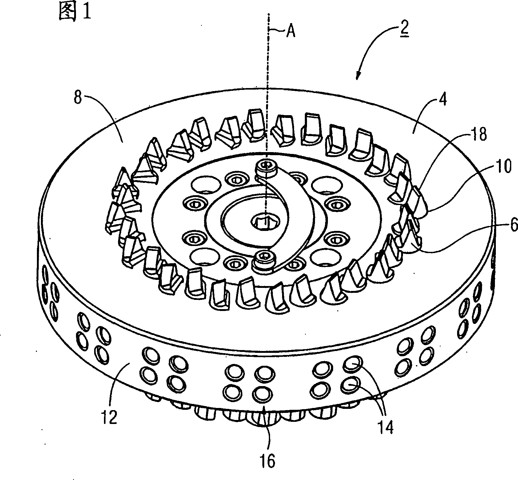
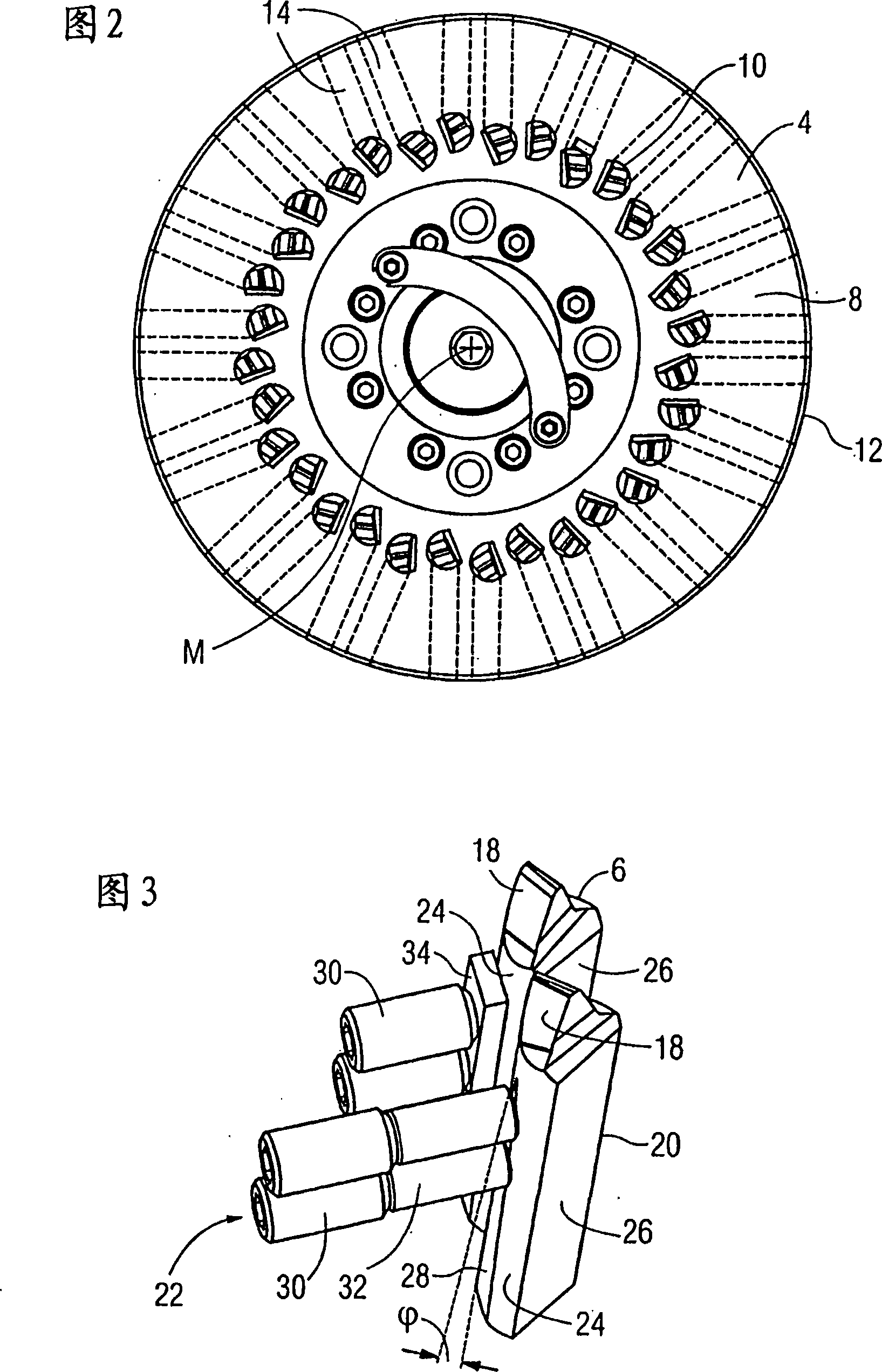
[0026] FIG. 1 shows a cutting head 2 which consists of a disc-shaped, one-piece cutting holder 4 and a plurality of rod-shaped cutting tools 6 . The tool holder 4 is rotatable about the axis A of rotation of the disk. The tool holder has a working surface 8 with a plurality of tool seats 10 in which rod-shaped tools 6 are accommodated. The disk rotation axis A extends through the midpoint M of the tool holder 4 . The tool holders 10 are arranged in pairs in an annular manner around the midpoint M of the disk-shaped tool holder 4 . The seat 10 is formed by etching and has an arcuate cross-section. Furthermore, the tool holder 4 has a peripheral surface 12 on which two rows of fastening holes 14 are formed, which extend approximately in the radial direction of the axis A of rotation of the disk. The lower row of fixing holes is arranged directly below the upper row of fixing holes, thereby forming a column 16 composed of two fixing holes 14 . The number of columns 16 corresp...


PUM


Abstract

The cutter head (2) includes a disc-shaped cutter holder (4) and a plurality of rod-shaped cutters (6) with handles (20). The disk-shaped tool holder (4) has a plurality of tool seats (10), into which tool holders (20) of rod-shaped tools (6) are inserted. The handle (20) has an arcuate cross-section. In order to achieve a simple and reliable fixing of the rod-shaped tool (6) in the tool seat (10), the tool seat (10) complementary to the rod-shaped tool (6) has an arcuate cross-section, so that the rod-shaped tool (6) Insert into the knife seat (10) with its knife handle (20) respectively precisely. The non-positive fastening is only achieved by pressing the clamping screw (22) of the rod-shaped tool (6).

Description

technical field [0001] The invention relates to a tool head with a disc-shaped tool holder, comprising a plurality of tool seats and a plurality of rod-shaped knives with handles, which are inserted into the tool seats through their handles, and their The handle has an arcuate cross-section. Background technique [0002] Such a cutter head for meshing with bevel gears is known from DE 101 12 165 B4. The tool holder described here has a tool seat whose cross-sectional geometry consists of a semicircle and a prism. The semi-circular cross-sectional geometry is used to accommodate a rod-shaped tool. The prismatic cross-sectional geometry serves to insert a clamping wedge into which the rod-shaped tool is held. In addition, clamping screws are provided for securing the clamping wedge. [0003] EP 0 813 927 A2 discloses a tool head provided with a cylindrical seat for receiving a substantially circular tool holder. In order to fasten these round tool holders, approximately r...

Claims


Application Information

Patent Timeline
Patent Type & Authority Applications(China)
IPC IPC(8): B23F21/22B23C5/22
CPCB23F21/226Y10T407/1735
Inventor D·米尔弗里德尔
Owner KENNAMETAL INC
Why Eureka
Try Eureka