S-type fluid bed

A fluidized bed and wave-shaped technology, applied in the field of fluidized bed, can solve the problems of particle blockage, pressure loss, particle back-mixing, etc., and achieve the effect of reducing blockage, pressure loss and wall wear

Inactive Publication Date: 2008-07-16
褚开维 +1
View PDF0 Cites 5 Cited by
  • Summary
  • Abstract
  • Description
  • Claims
  • Application Information

AI Technical Summary

Problems solved by technology

The flow phenomenon of "center-pipe wall flow" causes large pressure loss, particle back-mixing, particle clogging and serious wall wear problems to the whole system

Method used


Image

  • S-type fluid bed
  • S-type fluid bed

Examples


Embodiment Construction

[0030] The present invention is applicable to the pneumatic conveying system of the straight pipe, and is more applicable to the circulating fluidized bed system.

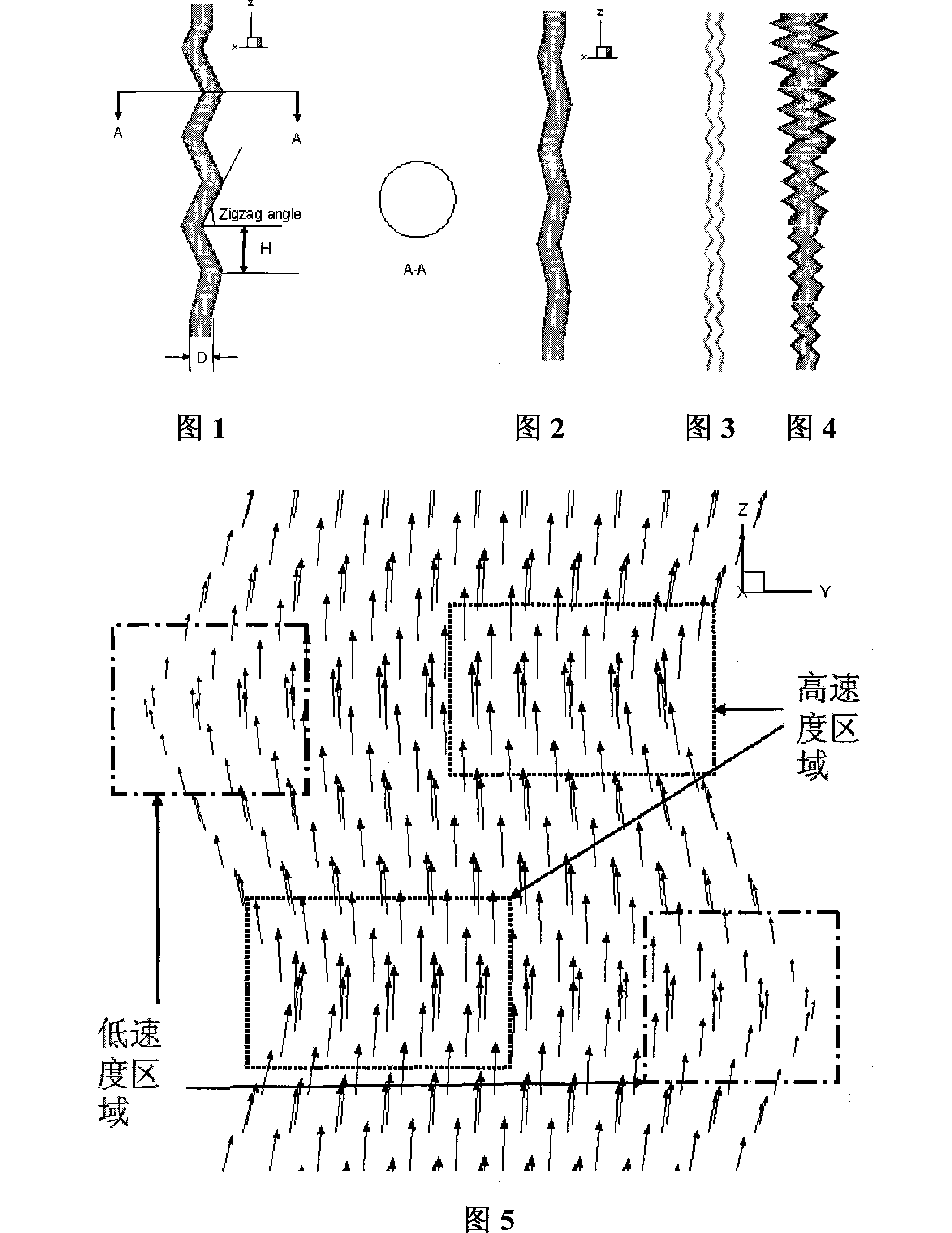
[0031] The cross-sectional shape of the S-type fluidized bed of the present invention is preferably a circle or a square, and may also be an ellipse, a rectangle or other regular polygons.

[0032] When the cross-section of the S-type fluidized bed of the present invention is a regular polygon, said inner wall is composed of sides of the polygon, wherein at least two symmetrical inner walls are wavy.

[0033] When the section of the S-type fluidized bed of the present invention is a circle or an ellipse, the symmetrical inner wall surface is wavy.

[0034] In all S-type fluidized beds, the wavy inner walls preferably appear in pairs symmetrically and parallel to each other.

[0035] Referring to Figures 1-4, the axial height (H) of the S-type fluidized bed of the present invention refers to the distance in the z-d...


PUM


Abstract

The invention relates to an S-shape fluidized bed with the main technical solving proposal that the inner wall surface of the fluidized bed shows the wave shape along the direction of a long axle. The invention aims at solving the problems of the fluidized bed such as pressure loss, granules mixing, granules build-up and serious wall surface abrasion caused by the phenomenon of 'center-wall pipe flow' in the background technology, providing the S-shape fluidized bed which has even distribution of flow phase speed, solid granules phase speed and concentration.

Description

technical field [0001] The invention relates to a fluidized bed, in particular to an S-type fluidized bed in a circulation system. Background technique [0002] Circulating fluidized bed technology is widely used in thermal crackers, such as petroleum catalytic crackers, thermal power generation, boiler combustion, waste incineration and cement precalciner. Generally speaking, a circulating fluidized bed system consists of a fluidized bed, a cyclone, a pipe from the top of the fluidized bed to the inlet of the cyclone, and a pipe from the bottom of the cyclone to the bottom of the fluidized bed. [0003] In a circulating fluidized bed system, oil, coal or catalyst enters from the bottom of the fluidized bed and enters the cyclone from the top of the fluidized bed. Part of the coal or catalyst entering the cyclone goes out from the top of the cyclone, and the other part enters the bottom of the fluidized bed from the bottom of the cyclone for recirculation. [0004] In petr...

Claims


Application Information

Patent Timeline
Patent Type & Authority Applications(China)
IPC IPC(8): B01J8/24
Inventor 褚开维余艾冰
Owner 褚开维
Why Eureka
Try Eureka