
Apparatus for positioning mine prop by increasing pressure

A mine pillar and pressure technology, applied in the direction of pillar/bracket, mining equipment, mine roof support, etc., can solve the problems of high cost and achieve the effect of low manufacturing cost and compact structure

Inactive Publication Date: 2008-07-16
MARCO SYSTEMANALYSE UND ENTWICKLUNG GMBH
View PDF0 Cites 0 Cited by
  • Summary
  • Abstract
  • Description
  • Claims
  • Application Information

AI Technical Summary

Problems solved by technology

For this purpose, a switching piston is also known in the prior art, which is controlled via a plurality of control valves, but this in turn entails relatively high costs

Method used


Image

  • Apparatus for positioning mine prop by increasing pressure

Examples


Embodiment Construction

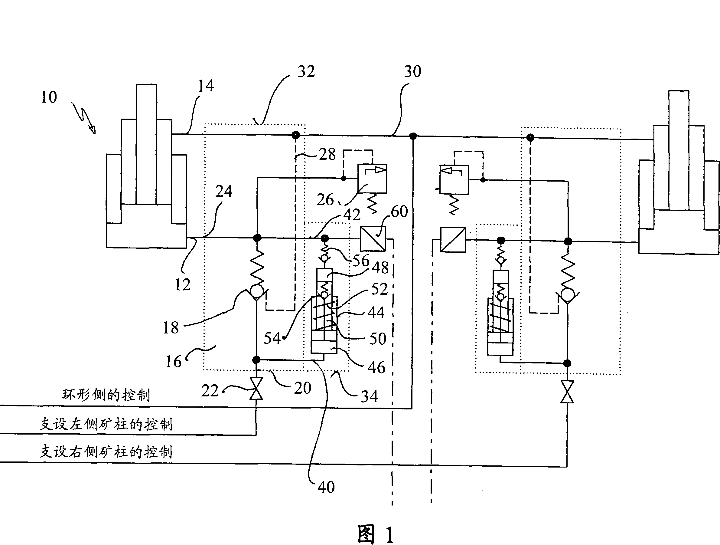
[0017] The figure shows a pillar 10 of a face support frame with a piston-side connection 12 for supporting the pillar and a ring-side connection 14 for recovering the pillar. The control of the pillar 10 takes place via a pillar valve 16 which has an openable non-return valve 18 inside it. The openable non-return valve 18 is closed in the direction of the inlet 20 of the pillar valve 16 , which is provided with an electrohydraulic abutment pressure via a plug 22 . The outlet 24 of the pillar valve 16 is connected to the piston-side connection 12 of the pillar 10 and is connected to an openable check valve 18 which is closed in the direction of the inlet 20 . A pressure relief valve 26 is additionally connected to the outlet-side connection 24 of the pillar valve. The openable non-return valve 18 is connected via a control channel 28 to the annular-side port 14 of the pillar 10 , wherein this port is connected to the electrohydraulic control unit via a line 30 , via which the...


PUM


Abstract

A device for supporting ore pillars with increased pressure, the device includes: an inlet and an outlet; a plunger hydraulic cylinder arranged therebetween, and the plunger hydraulic cylinder can realize pressure conversion. The working piston of the plunger cylinder is biased by a spring and has a bypass check valve between its two annular chambers.

Description

technical field [0001] The present invention relates to a device for supporting pillars with increased pressure. Such devices are known in underground mining in order to transfer the pressure of the pillars of the face support frame to a higher level. A higher support force is desirable in many face installations, since this increases the efficiency of the support. The purpose of the supports is to prevent the destruction of the covering rock and especially the roof at the mining site. For this purpose, the hydraulic system is designed to a system pressure of approximately 300 to 350 bar. In the pillars of the face support frame, the pressure of 420 to 480 bar is set as the upper limit. If no special device is provided, generally the covering rock will sink, until the upper limit of pressure is reached, until the bulldozing blade (Schild) will increase to the maximum resistance. Background technique [0002] In order to provide increased pressure, it is known to provide ...

Claims


Application Information

Patent Timeline
Patent Type & Authority Applications(China)
IPC IPC(8): E21D15/51
CPCE21D15/585E21D23/26
Inventor 马丁·路透
Owner MARCO SYSTEMANALYSE UND ENTWICKLUNG GMBH
Learn More