
Novel flame generating means

A generator and flame technology, applied in combustion ignition, lighting and heating equipment, combustion methods, etc., can solve the problems of difficult design and manufacture, and achieve significant energy saving, simple structure, and low cost

Active Publication Date: 2010-06-16
GUANGDONG HAIRONG ENVIRONMENTAL PROTECTION TECH CO LTD
View PDF4 Cites 0 Cited by
  • Summary
  • Abstract
  • Description
  • Claims
  • Application Information

AI Technical Summary

Problems solved by technology

However, plasma ignition technology and high-frequency ignition technology are more difficult to design and manufacture in terms of high-power products exceeding 250kw

Method used


Image

  • Novel flame generating means
  • Novel flame generating means
  • Novel flame generating means

Examples


Embodiment Construction

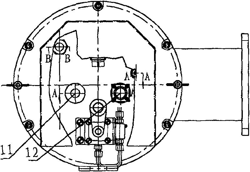
[0016] The structure of novel flame generator of the present invention is as figure 1 As shown, it is mainly composed of the following six parts: 1. Pipeline 5. Second, vaporizer 6. 3. Shell: including machine cover 3, bellows 4 and other parts. Four, air distribution device: including air distribution cylinder 7, preheating ring 9, heat insulation cover 10 and other parts. 5. Detection mechanism: including fire viewing hole 11, visible light flame detection probe 12 and other pieces. 6. Ignition mechanism: including connecting plate 1, cylinder 2, ignition gun 8 and other parts.

[0017] The second part of the above six components, that is, the unique working characteristics of the gasifier, makes the working principle of the present invention unique and novel, and the performance has better excellence. The gasifier 6 is formed by sintering the metal powder 6-3 filled with the central preheating rod 6-1 and the outer sleeve 6-2. 6-1 The outer diameter of the central preh...


PUM


Abstract

The invention discloses a novel flame generator, comprising a casing formed by a back-end hood, a middle air box and a front air distributing cylinder and an ignition gun, an oil feeding tube and an evapourator which are arranged in the casing. The evapourator is formed by filling metal powder between a central pre-heating bar and an outer sleeve and agglomerating the two parts, and capillary holes formed by the powder metallurgy in the evapourator form the flow channel of diesel oil. The evapourator is fixed in the air distributing cylinder, and a long pre-ignition chamber is arranged in theair distributing cylinder at the far end of the evapourator, and an ignition gun port is arranged in the pre-ignition chamber when in ignition process. The side surface of the air distributing cylinder is provided with a combustion supporting air inlet, and a combustion supporting passage is arranged between the evapourator and the air distributing cylinder. The oil inlet tube comprises a pre-heating ring which is additionally arranged close to the port but at the far end of the air distributing device and the oil inlet tube. The fuel firstly passes the pre-heating ring, then enters the evapourator, and then is ejected from the far end of the evapourator. The novel flame generator can cover the power range which can be achieved by an oil gun, a plasma igniter and a high frequency inductiveigniter, with distinct oil conserving effect, high safety factor and less required site pipe-reconstructing workload.

Description

technical field [0001] The invention relates to a fuel oil device-flame generator applied to coal-fired generator sets in thermal power plants of various sizes. Background technique [0002] At present, there is no small oil gun power plant with an output of less than 16kg / h (equivalent power is 200kw) in China. In order to further save fuel, many enterprises and scientific research institutions have successively developed high-tech products such as plasma ignition and high-frequency induction ignition. The power is generally around 150kw to 250kw. This power range just makes up for the lack of low-power oil guns. Moreover, it has been popularized and applied in power plants and has achieved good results. However, plasma ignition technology and high-frequency ignition technology are more difficult to design and manufacture in terms of high-power products exceeding 250kw. For this reason, as early as 2005, our company has established a project to develop a new type of ignit...

Claims


Application Information

Patent Timeline
Patent Type & Authority Patents(China)
IPC IPC(8): F23Q13/02
Inventor 曹琴王雨勃杨生贵孙继国任志鹏贾锦孙树翁
Owner GUANGDONG HAIRONG ENVIRONMENTAL PROTECTION TECH CO LTD
Learn More