

Portable fast joint inspection device for multiple tumor tokens
A tumor marker, portable technology, applied in the field of portable rapid joint inspection devices, can solve the problems of single index detection, unfavorable environmental protection treatment, pollution of the environment, etc., to achieve the effect of facilitating quality control and avoiding detection cross-interference
- Summary
- Abstract
- Description
- Claims
- Application Information
AI Technical Summary
Problems solved by technology
Method used
Image

Examples
Embodiment 1
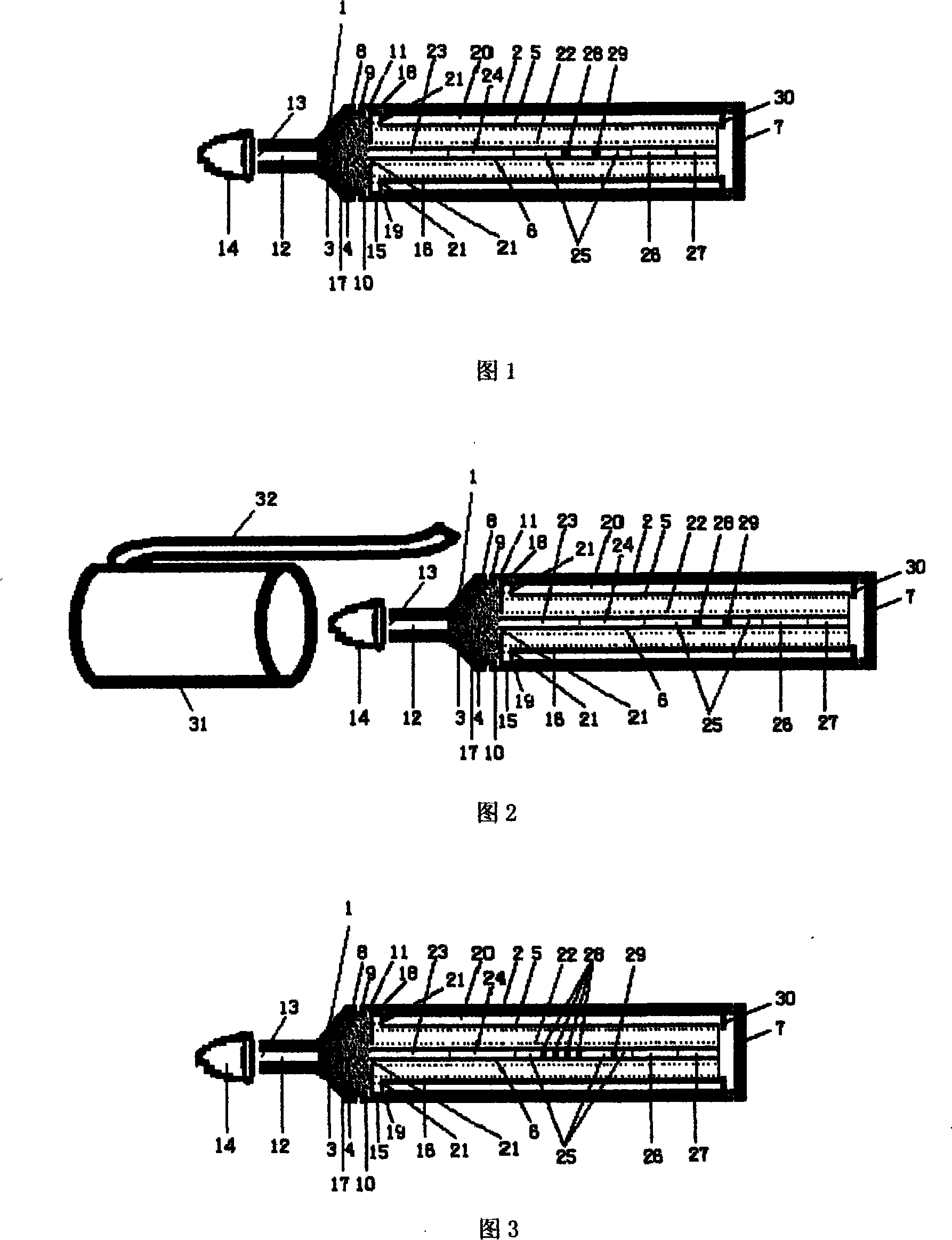
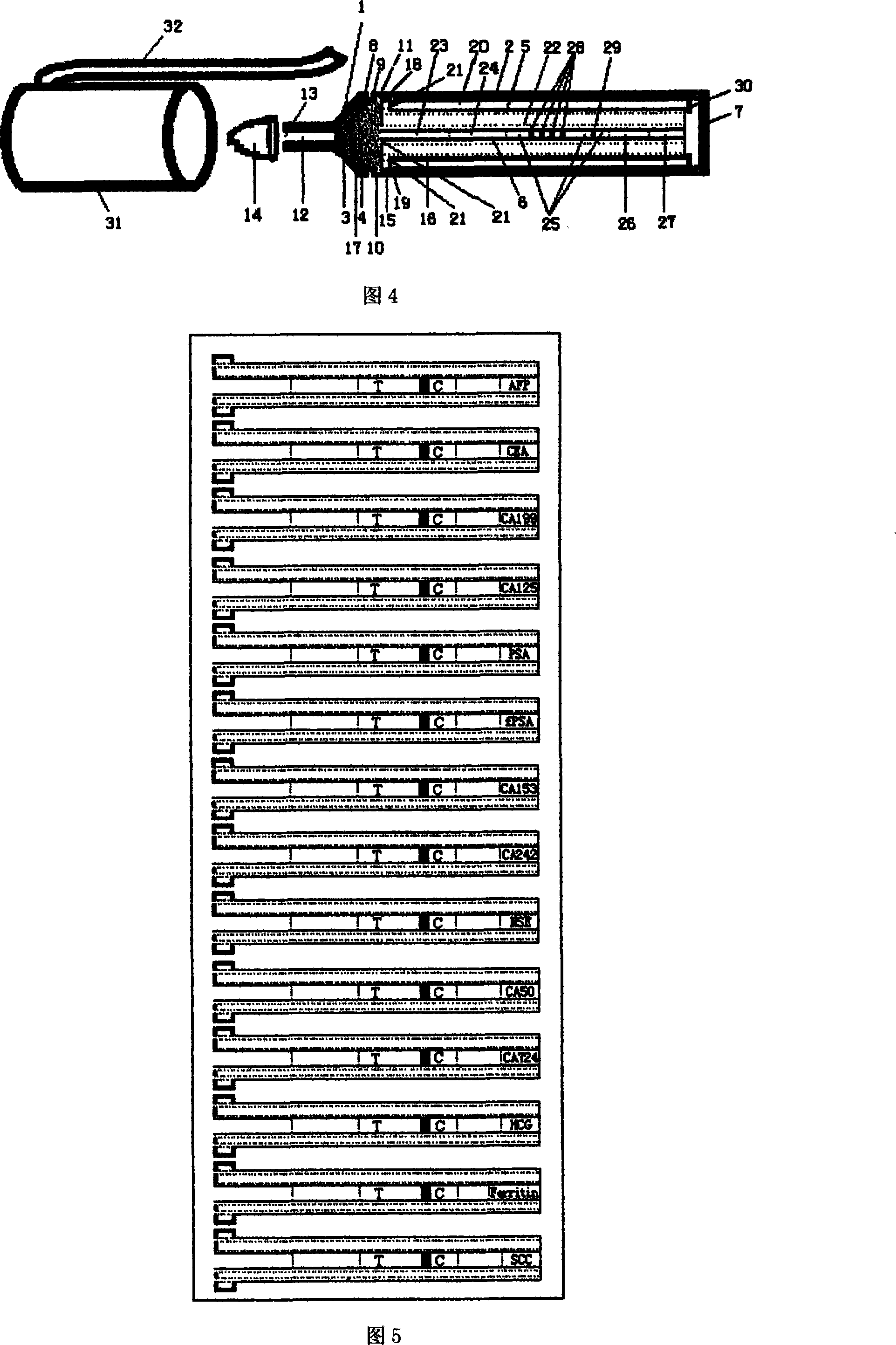
[0077] Example 1 The structure of a portable multiple tumor marker rapid joint detection device (illustrated in conjunction with Figures 1-4)
[0078] Fig. 1 is a side view of the structure of a portable multi-tumor marker rapid joint detection device composed of a single-index detection test strip with a single detection line. The quality control line 29 of the detection color development area 25 of the test strip in the device is separated by a certain distance. A detection line 28 is set at a distance, and an antibody of a tumor marker antigen is respectively captured at each detection line position.
[0079] The device includes a sample suction head 1 and a detection tube 2 connected to the back end of the sample suction head 1 .
[0080] A capillary suction nozzle 12 is arranged at the front end of the suction head 1 . The suction nozzle 12 is provided with a sample suction port 13 for sample suction. The front end of the suction nozzle 12 can be covered with a rubber p...
Embodiment 2
[0100] Example 2 Operation method of portable multi-tumor marker rapid combined detection device
[0101] The operation and use method of the portable multiple tumor marker rapid joint detection device described in the present invention is as follows:
[0102] (1) Take out the quick joint inspection device;
[0103] (2) Remove the device head cover 31 of the device and the rubber cap 14 at the front end of the suction head to expose the sample suction port 13, and dip the suction nozzle 12 into the inspection product;
[0104] (3) within a few minutes, observe the sample color development area 25 built-in test strip quality control line 29 and detection line 28 in the transparent plastic shell of the device detection tube. The negative and positive test results of each index of the product. The test strip detection line 28 and the quality control line 2g display a red line, and the test result is positive; the quality control line 29 shows a red line, and the test line 28 ha...
Embodiment 3
[0105] Example 3 Application of Portable Multiple Tumor Markers Rapid Joint Detection Device in Rapid Joint Detection of Blood Tumor Markers in Outpatients
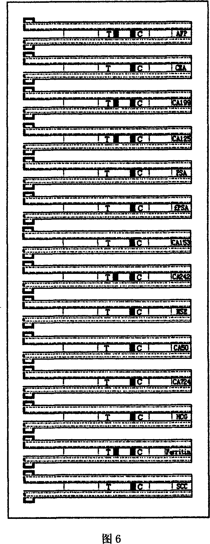
[0106] The test strips fixed in each single groove of each surface shallow groove 22 of the test paper fixing column 5 of the joint inspection device in separate slots can be multiple single-index detection test strips with a single detection line, or can be 1 to many A multi-indicator joint test strip with multiple detection lines.
PUM
 Abstract
Description
Claims
Application Information