Parallel type macro-micro-driven high-precision heavy-caliber optical grating split joint device
A technology of large-diameter grating and macro-micro drive, which is applied in installation, optics, optical components, etc., can solve the problem of no high-precision large-diameter grating splicing device, and achieve the effect of compact structure, high splicing precision, and high-precision splicing
- Summary
- Abstract
- Description
- Claims
- Application Information
AI Technical Summary
Problems solved by technology
Method used
Image
Examples
specific Embodiment approach 1
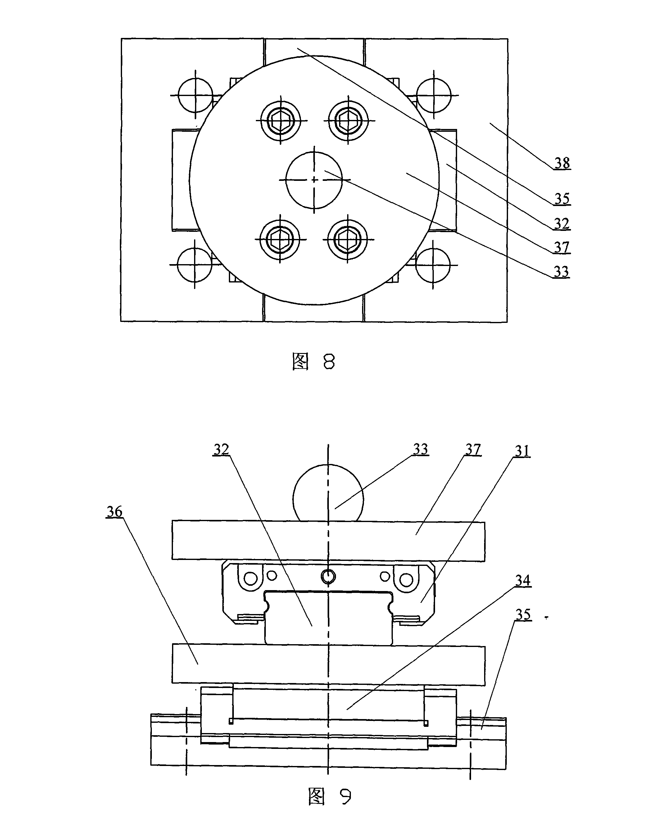
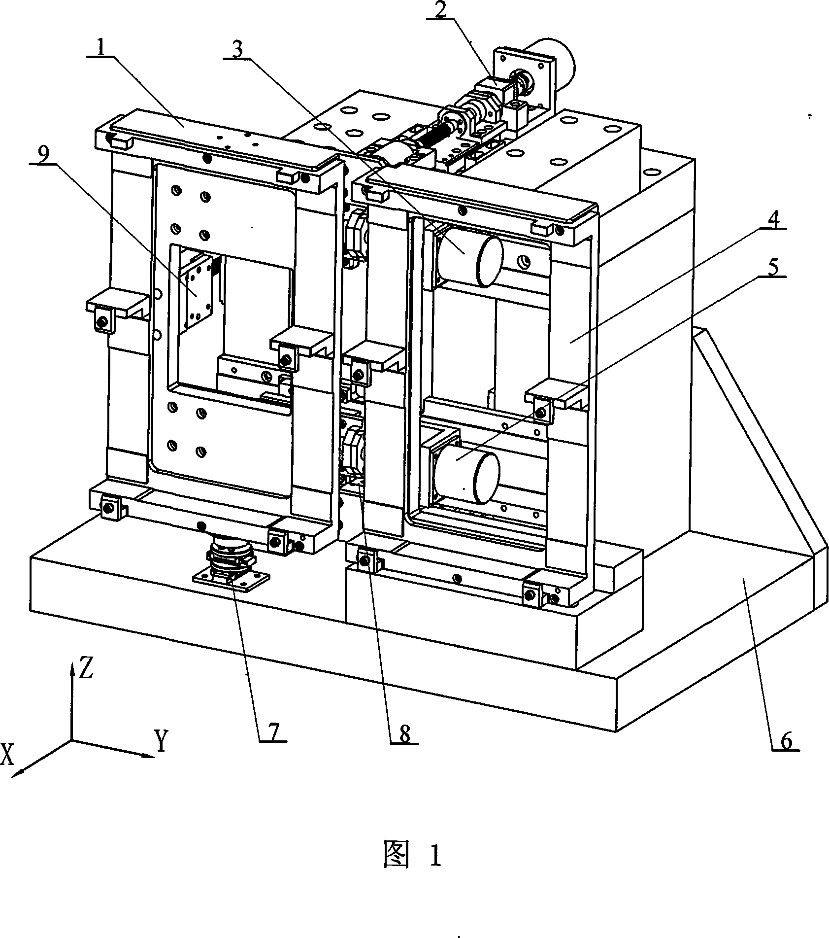
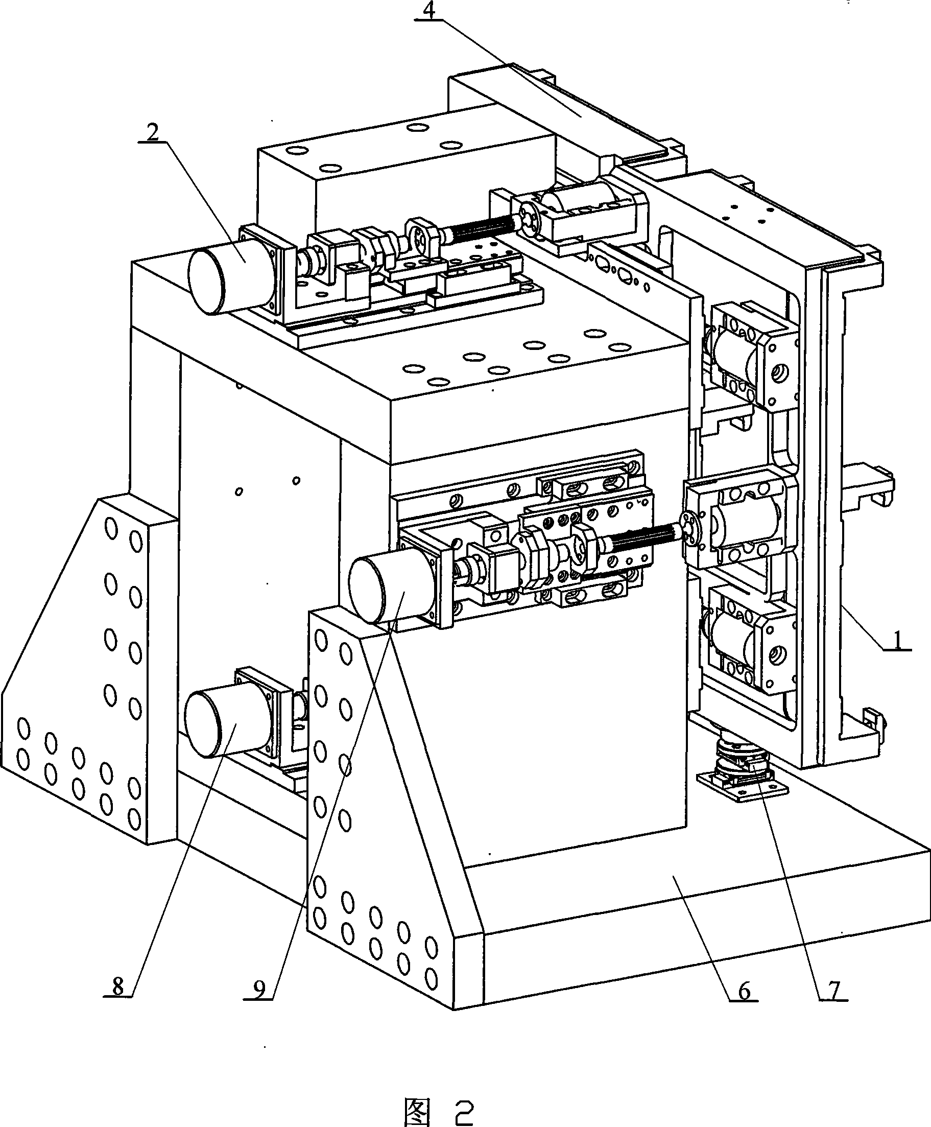
[0010] Specific Embodiment 1: This embodiment is described in conjunction with Fig. 1 and Fig. 2, and this embodiment is composed of a moving grating component 1, a fixed grating component 4, five linear drives, a two-dimensional motion platform component 7, and a base 6; the two The three-dimensional motion platform component 7 is fixed on the base 6, the lower end of the moving grating component 1 is ball-hinged with the upper end of the two-dimensional motion platform component 7, the fixed grating component 4 is fixed on the base 6, and the five The linear drives are respectively the first X-axis linear drive 2, the second X-axis linear drive 8, the third X-axis linear drive 9, the first Y-axis linear drive 3, and the second Y-axis linear drive 5. The first X-axis The linear driver 2, the third X-axis linear driver 9, and the second X-axis linear driver 8 are sequentially arranged on the base 6 along the X-axis direction from top to bottom. The first Y-axis linear driver 3,...
specific Embodiment approach 2
[0011] Specific Embodiment 2: This embodiment is described in conjunction with Fig. 1 and Fig. 3. Each linear actuator in this embodiment consists of a flexible connecting shaft 10, a micro-motion flexible hinge part 11, a screw base 12, a macro-motion screw 13, a macro-motion Stepping motor 14, flexible coupling 15, bearing seat parts 16, screw nut 17, macro-movement locking piece 18, macro-dynamic and static linear guide 19, macro-dynamic and dynamic linear guide 20, driver base 21, locking pad 22 The two ends of the flexible connecting shaft 10 are respectively connected with the micro-motion flexible hinge part 11 and the screw nut seat 12, and the input end of the macro-moving screw 13 passes through the inner threaded hole of the screw nut seat 12 and the screw nut 17 And the shaft hole of the bearing seat part 16 is connected to the output end of the flexible coupling 15, the input end of the flexible coupling 15 is connected to the output shaft of the macro-motion stepp...
specific Embodiment approach 3
[0012] Specific Embodiment 3: This embodiment is described with reference to FIG. 4 . The macro-motion locking member 18 of this embodiment is provided with an arc-shaped groove 23 . Such a design can ensure proper micro-deformation between the two parts of the macro-movement locking member 18 and the locking pad 22 during locking, so as to realize the locking of the macro-motion movement.
PUM
 Abstract
Description
Claims
Application Information
 - R&D
- Intellectual Property
- Life Sciences
- Materials
- Tech Scout
- Unparalleled Data Quality
- Higher Quality Content
- 60% Fewer Hallucinations
Browse by: Latest US Patents, China's latest patents, Technical Efficacy Thesaurus, Application Domain, Technology Topic, Popular Technical Reports.
© 2025 PatSnap. All rights reserved.Legal|Privacy policy|Modern Slavery Act Transparency Statement|Sitemap|About US| Contact US: help@patsnap.com


