

Optical beam parameter product symmetrization device of semiconductor laser array fast and slow axis
A technology of laser array and parameter product, applied in the field of laser technology application, can solve problems such as difficult assembly and difficult adjustment
- Summary
- Abstract
- Description
- Claims
- Application Information
AI Technical Summary
Problems solved by technology
Method used
Image

Examples
Embodiment 1
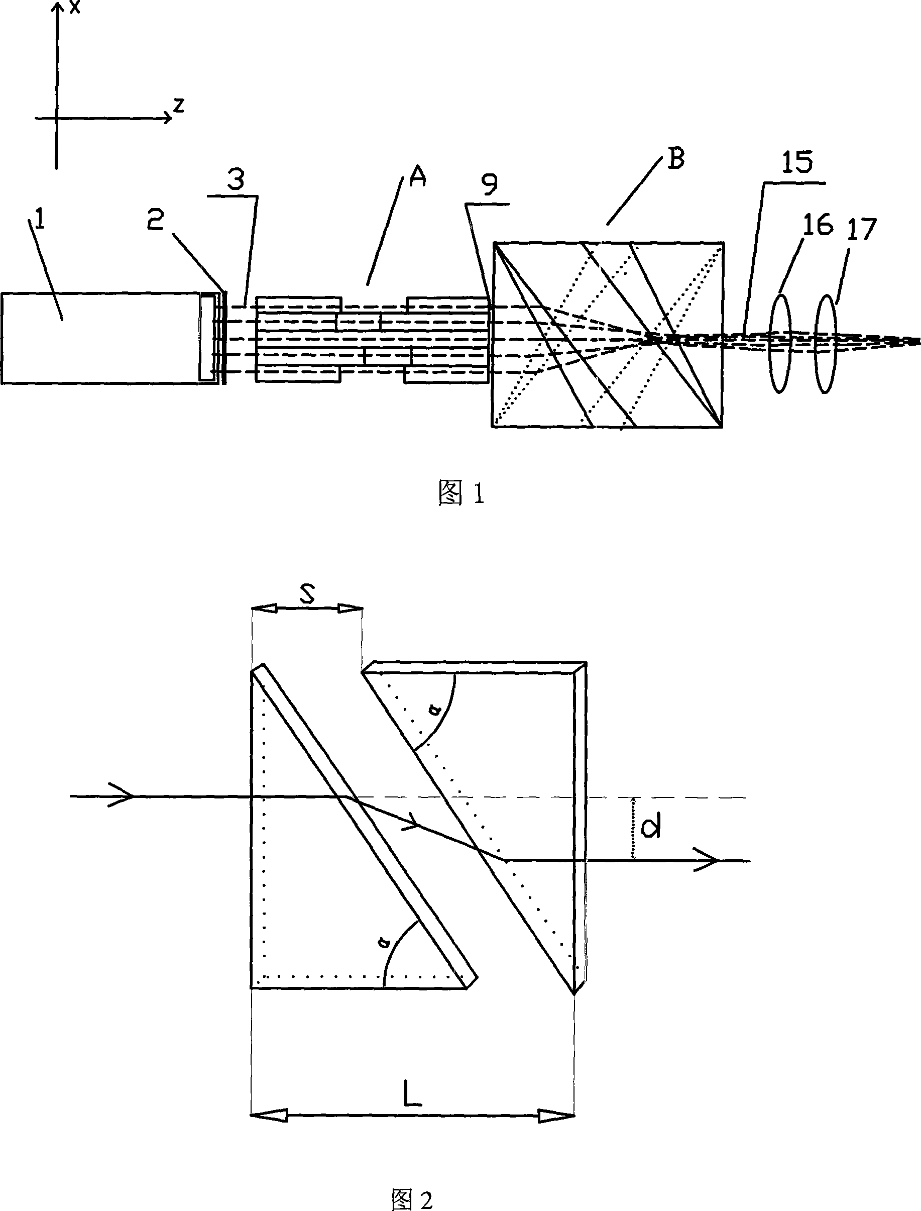
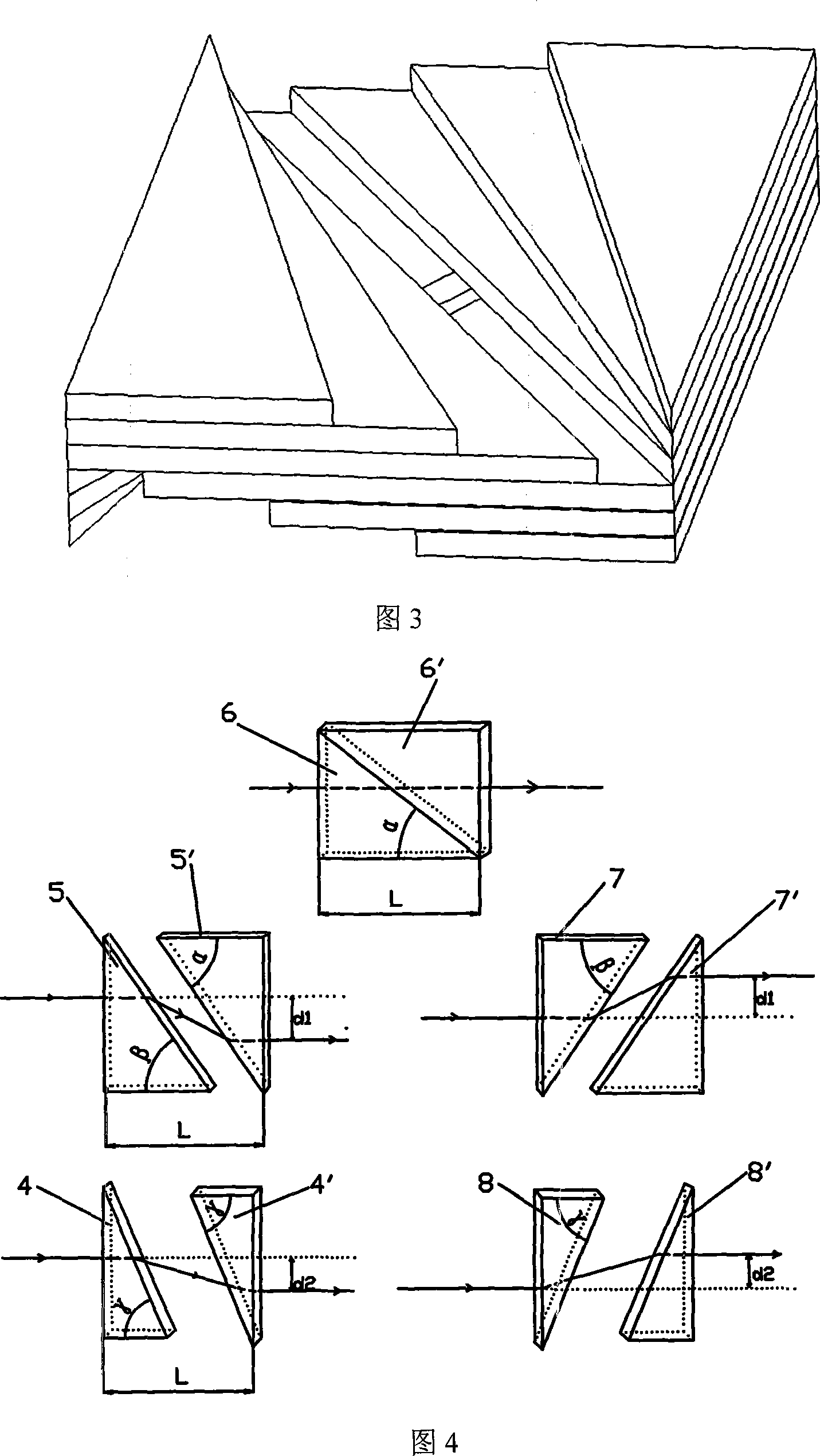
[0065] For a one-dimensional array, its device includes a semiconductor laser one-dimensional array 1, the first microlens array 2 for collimating the fast and slow axes, the first flat glass stack A and the second flat glass stack B, and consists of a cylindrical lens 16 and a spherical lens 17. The focus lens group, as shown in Figure 1. In the figure: x is the direction of the slow axis of the one-dimensional array, y is the direction of the fast axis of the one-dimensional array, and z is the beam transmission direction. The first stack of flat glass A and the second stack of flat glass B are composed of 5 pairs of glass plates stacked together in sequence along the thickness direction of the glass plates, wherein each pair of glass plates includes two identical right-angled triangles. Glass plate, two right triangle glass plates are placed on the same level, so that the light beam emitted from the hypotenuse of the previous triangular glass plate can be incident on the hy...
Embodiment 2
[0073] The difference between this embodiment and Embodiment 1 is that the first flat glass stack A and the second flat glass stack B adopt the method of changing the size, and the other structures are completely the same.
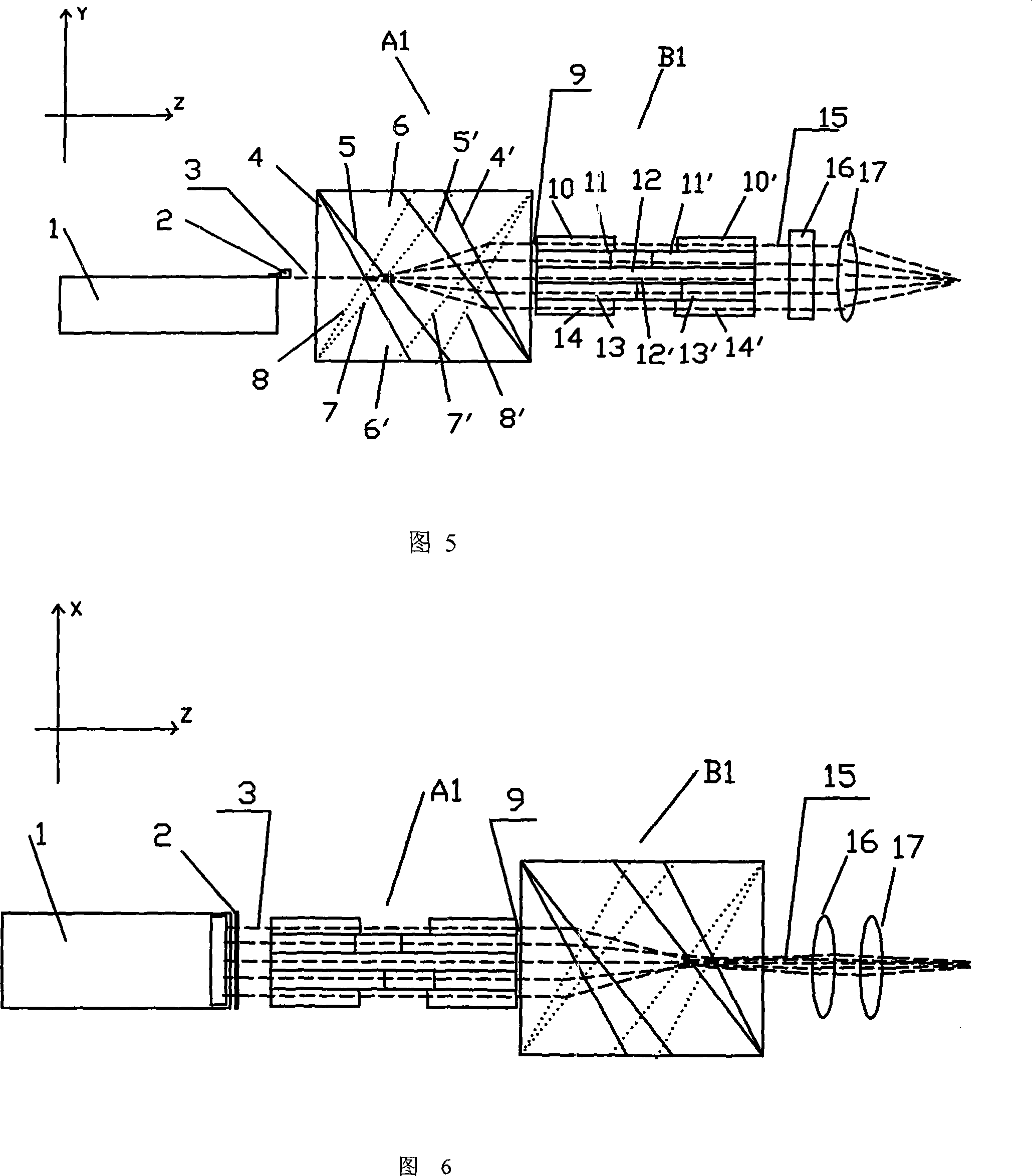
[0074] The principle of changing the size method: the total length L of each pair of triangular glass plates is constant, by changing the length of the triangle base but keeping the bottom angle unchanged, so that the propagating light beam is transmitted between each pair of triangular glass plates despite the same refraction angle Different distances result in different offsets, as shown in Figure 9. For the one-dimensional array, the shaping principle of the method of changing the size is the same as that of the method of changing the angle in Embodiment 1: the light beam 3 collimated by the fast and slow axis collimating microlens is vertically incident on the triangular plate glass stack A2, and the light beam is divided into five parts and A refracti...
Embodiment 3
[0076] The difference between this embodiment and Embodiments 1 and 2 is that the first flat glass stack A and the second flat glass stack B adopt the distance changing method, and the other structures are identical.
[0077] The principle of changing the distance method: all the triangular glass plates in each group in the first flat glass stack A and the second flat glass stack B are exactly the same, and the beam is generated by changing the relative displacement S of each pair in the horizontal direction. Different offsets, as shown in Figure 13. For the one-dimensional array, the shaping principle of the method of changing the distance is the same as that of the method of changing the angle and the method of changing the size in Embodiments 1 and 2: the light beam 3 collimated by the fast and slow axis collimating microlens is vertically incident on the triangular plate glass pile A3, and the light beam It is divided into five parts and a refraction offset is generated in...
PUM
 Abstract
Description
Claims
Application Information