Packed material large-slope lifting device

A technology with large slopes and materials, applied in the direction of transportation, packaging, conveyors, etc., can solve the problems of low operating reliability, occupying effective storage capacity, easy bag jamming at the tape interface, etc., to improve conveying speed and reliability, and improve work Efficiency, the effect of improving labor intensity

Inactive Publication Date: 2008-07-23
WUHAN INSTITUTE OF TECHNOLOGY
View PDF0 Cites 3 Cited by
  • Summary
  • Abstract
  • Description
  • Claims
  • Application Information

AI Technical Summary

Problems solved by technology

However, the belt conveyor loading system is rarely used at home and abroad. The main reason is that key technologies such as large-slope lifting of bagged materials in a confined space have not been broken through.
The maximum climbing angle of bagged materials transported by belts is generally less than 30°. If two belts are used to clamp and lift bagged materials, the material will flow toward the end due to the extrusion of the belts, and the end of the material bag may be burst; Lifting by steps with tapes with a small slope not only occupies the effective storage capacity, but also easily jams and breaks bags at the tape interface, resulting in low operational reliability

Method used


Image

  • Packed material large-slope lifting device
  • Packed material large-slope lifting device
  • Packed material large-slope lifting device

Examples


Embodiment 1

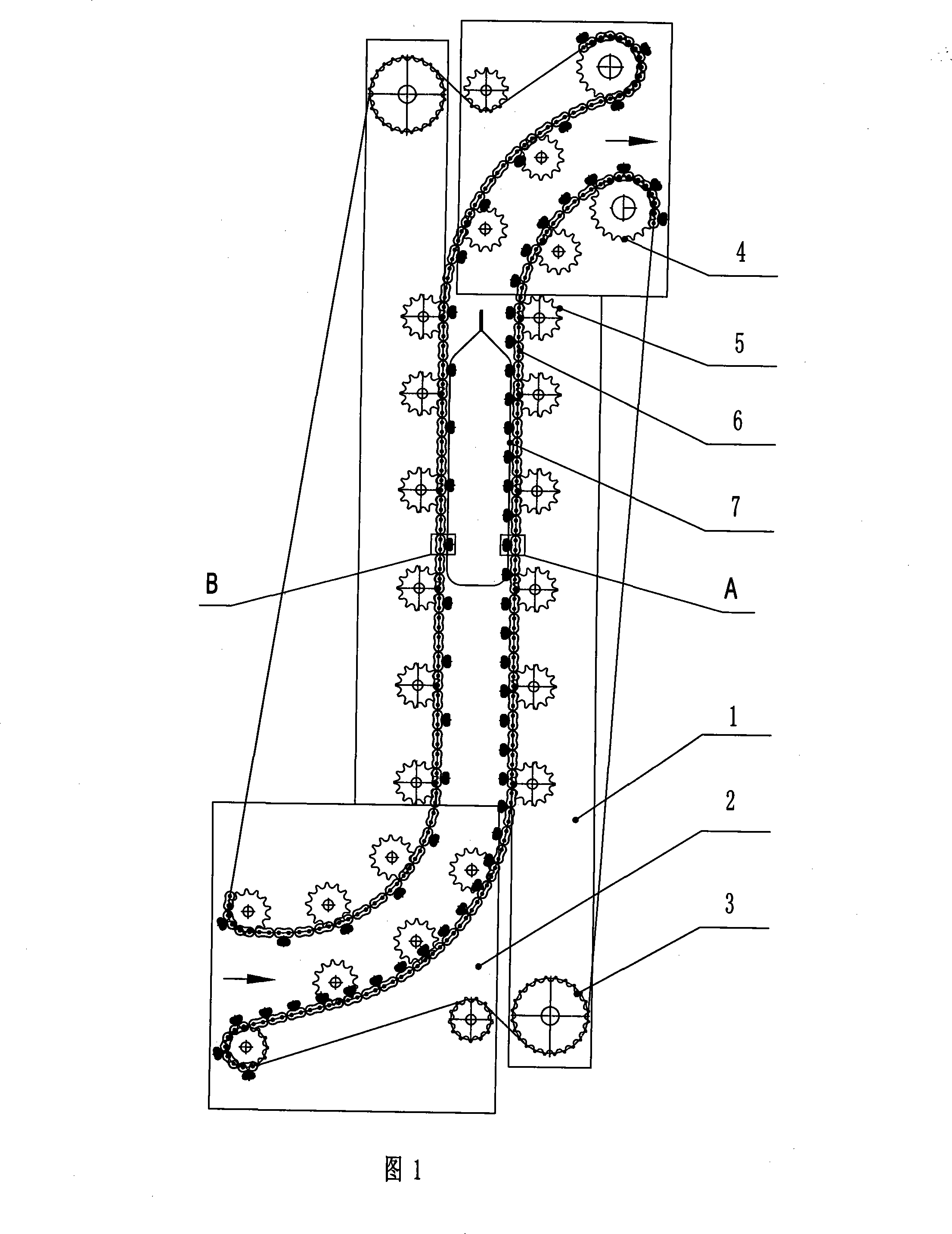
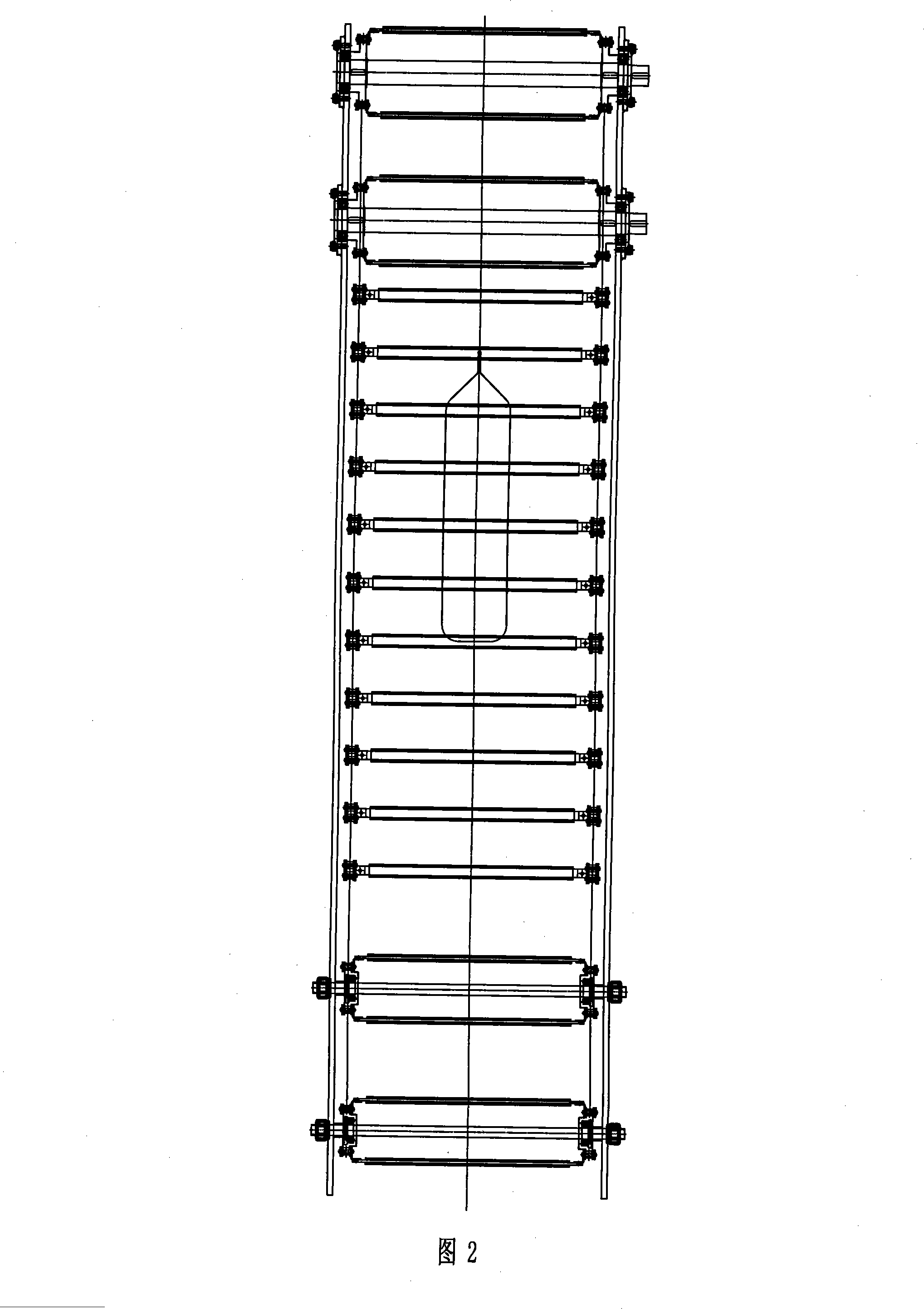
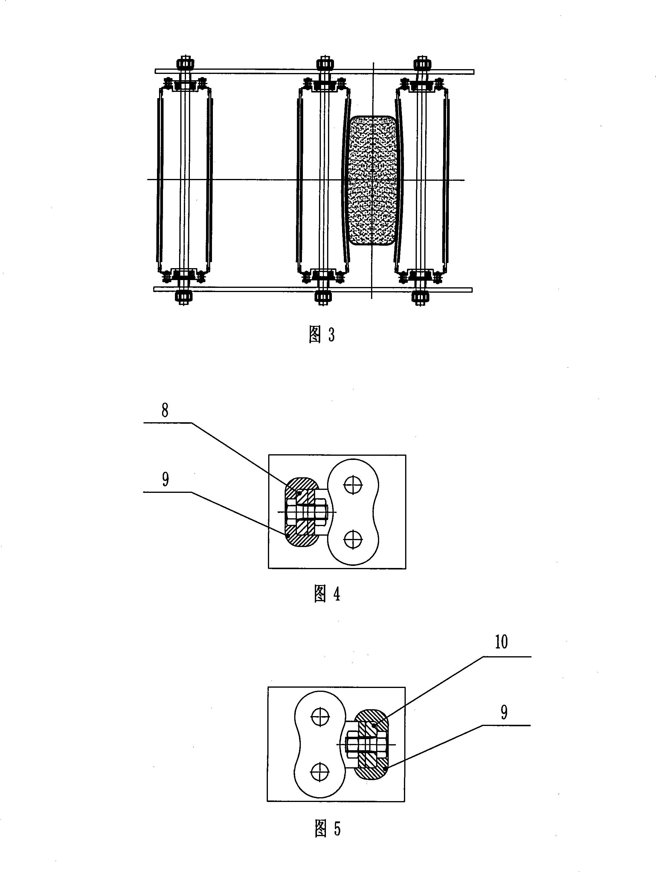
[0022] As shown in Figures 1-5, a large-slope lifting device for bagged materials includes a left frame 1, a right frame 2, drive sprockets, support sprockets and Tensioning sprocket, two sets of short-pitch conveying chains 6 are respectively engaged with the drive sprocket 4, supporting sprocket 5 and tensioning sprocket 3 provided on the left frame and the right frame to move in a circular motion. 6 are respectively hinged with a lower supporting plate 8 and an upper pressing plate 10 to form a lower supporting plate group and an upper pressing plate group, and the lower supporting plate group constitutes the supporting surface of the material bag. 60 mm, the distance between two adjacent upper platens of the upper platen group is relatively large, generally 80-160 mm, its function is to clamp the material bag in sections, so that the material bag is lifted synchronously with the upper platen and the lower supporting plate, and at the same time avoids bagging The inner mate...

Embodiment 2

[0026] The distance between two adjacent lower supporting plates is 50 mm, the distance between two adjacent upper pressing plates of the upper pressing plate group is 120 mm, the length of the hinged fulcrum at both ends of the upper pressing plate and the lower supporting plate is 1.8 times the width of the material bag, and the rest are the same Example 1.


PUM


Abstract

The invention relates to a high gradient lifting device, specifically speaking, a high gradient lifting device for bagged material, which includes a left frame and a right frame; each of the left frame and the right frame is respectively provided with a driving sprocket, a supporting sprocket and a tensioning sprocket; two sets of short-pitch transfer chains are respectively engaged and connected with the driving sprocket, the supporting sprocket and the tensioning sprocket arranged on the left frame and the right frame to make cycle motion. The invention is characterized in that a lower bolster and an upper pressure board are respectively articulated with the transfer chain so as to form a lower bolster group and an upper pressure plate group, an S-shaped bagged material lifting transfer passage is formed between the lower bolster group and the upper pressure plate group of the two transfer chains. The invention has the advantages that: (1) the device reduces the labor input, decreases the handling cost, and improves the labor intensity of the worker and the work efficiency; (2) the bag is difficult to be clamped or damaged; (3) the lifting transportation of bagged material can be realized within the angle range of 30-90 DEG and the transfer speed and the reliability of the bagged material can be effectively improved.

Description

technical field [0001] The invention relates to a large-slope lifting device, in particular to a large-slope lifting device for bagged materials. Background technique [0002] At present, the mechanized loading and unloading of bagged materials at home and abroad mainly adopts pallet forklifts and hanging bag lifting methods. Both of these two loading methods are discontinuous operations, and their main disadvantages are that pallets or hanging bags must be pre-laid before material stacking, and the pallets or hanging bags are transported with vehicles and ships, which makes recycling difficult, large consumption, and high loading and unloading costs. [0003] There is another way that bagged materials are transported and loaded by belts, which is a continuous operation and can share equipment with the stacking system, with low investment and operating costs. However, the belt conveyor loading system is rarely used at home and abroad. The main reason is that key technologie...

Claims


Application Information

Patent Timeline
IPC IPC(8): B65G17/00B65G17/30B65G17/46
Inventor 廖义德徐建民
Owner WUHAN INSTITUTE OF TECHNOLOGY
Why Eureka
Try Eureka