

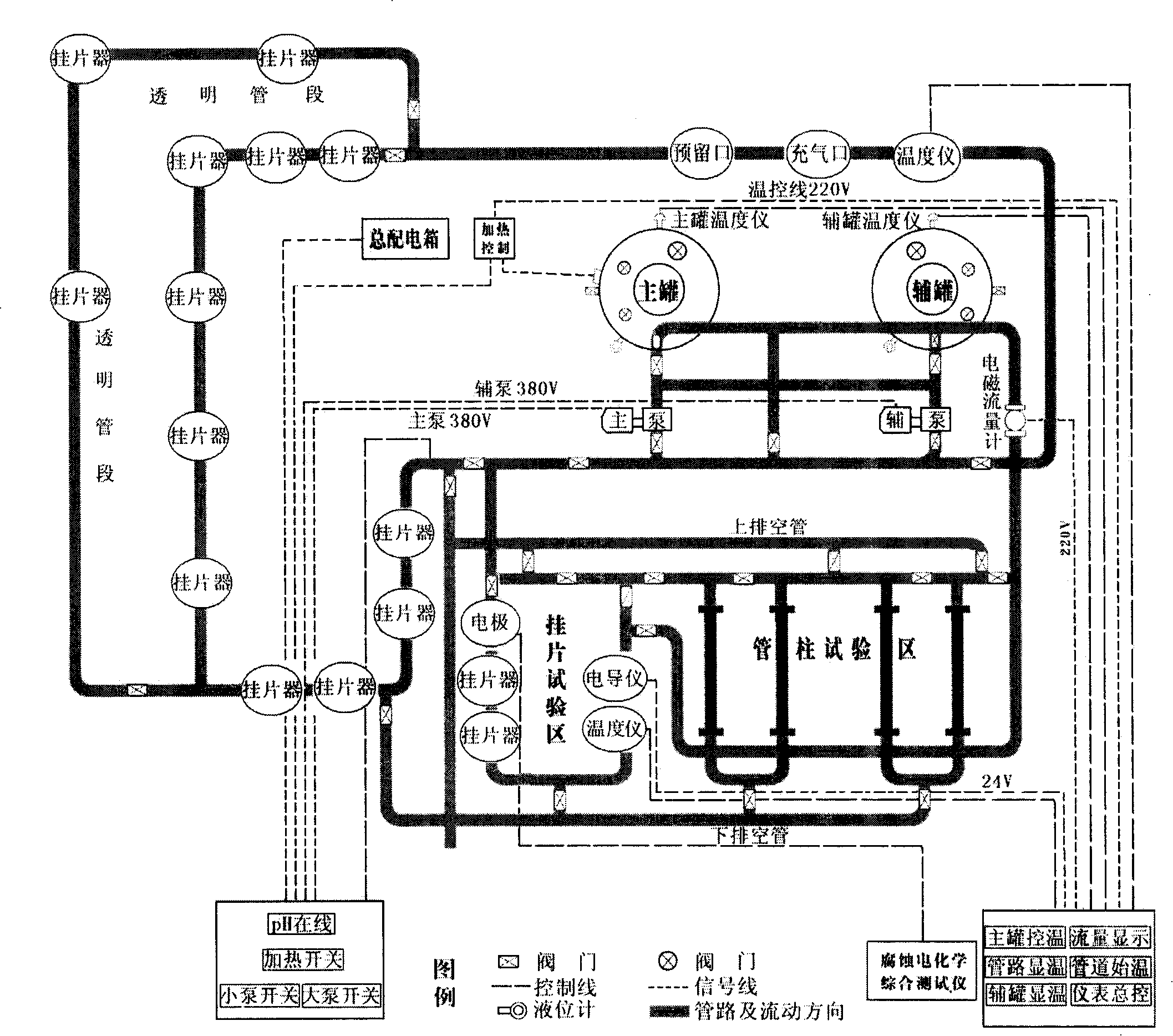
Dynamic simulation tester in erosion chamber
A dynamic simulation test and test device technology, applied to measuring devices, weather resistance/light resistance/corrosion resistance, instruments, etc., can solve problems such as waste of manpower, material and financial resources, long test period, and too simple design
- Summary
- Abstract
- Description
- Claims
- Application Information
AI Technical Summary
Problems solved by technology
Method used
Image

Examples
Embodiment Construction
[0015] In conjunction with accompanying drawing, the present invention is further described:
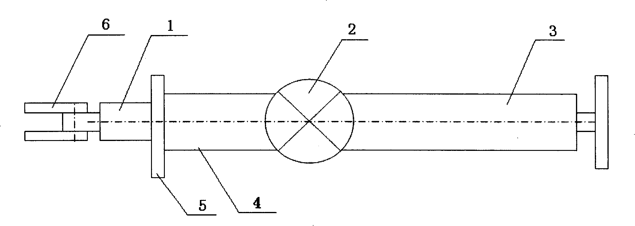
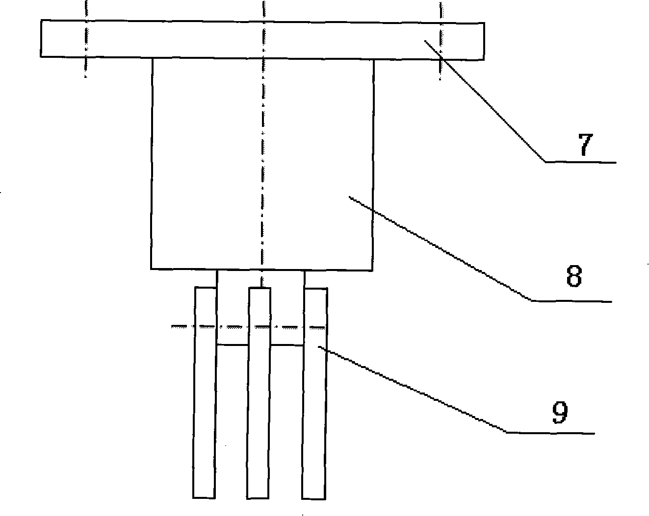
[0016] It consists of pipeline system, temperature control system, detection system, corrosion-resistant circulation pump, corrosion-resistant storage tank and control valve. The pipeline system is composed of PPR, PVC and plexiglass tubes, with inner diameters of φ65mm and φ100mm respectively, which can realize the corrosion test of two flow rates at the same time, and can observe the flow state of the corrosive medium and the state of the corrosion coupon online. The pipeline has high strength, good temperature resistance and corrosion resistance. 18 test ports are reserved on the pipeline, which is convenient for simultaneous comparative testing of corrosion test pieces of various materials and shapes, and electrochemical online detection of instantaneous corrosion rate. Test ports are also reserved at elbows and risers to facilitate detection and observation of corrosion characte...
PUM
| Property | Measurement | Unit |
|---|---|---|
| width | aaaaa | aaaaa |
| length | aaaaa | aaaaa |
| thickness | aaaaa | aaaaa |
Abstract
Description
Claims
Application Information