
Bunching type synthetic aperture laser radar imaging method

A synthetic aperture laser and radar imaging technology, applied in radio wave reflection/re-radiation, using re-radiation, measurement devices, etc., can solve problems such as undersampling in azimuth, long pulse width, and low pulse repetition frequency PRF

Inactive Publication Date: 2008-07-23
XIDIAN UNIV
View PDF0 Cites 42 Cited by
  • Summary
  • Abstract
  • Description
  • Claims
  • Application Information

AI Technical Summary

Problems solved by technology

However, the frequency modulation period of the LiDAR continuous wave signal is generally longer, that is, the pulse width is longer. In this way, due to the longer modulation period in the continuous transmission and reception of signals, the approximation of "one step and one stop" in SAR is no longer valid. The original algorithms based on this approximation will cause image defocus and translation to be inapplicable. At the same time, due to the long pulse modulation period of the SAL signal, which is equivalent to the low pulse repetition frequency PRF of the system, when the SAL system works in spotlight mode, The pulse repetition frequency will be smaller than the Doppler bandwidth in the azimuth direction, resulting in undersampling in the azimuth direction, and the phenomenon of image ghosting in the azimuth direction will appear
Therefore, no one has proposed a method suitable for synthetic aperture lidar imaging so far.

Method used


Image

  • Bunching type synthetic aperture laser radar imaging method
  • Bunching type synthetic aperture laser radar imaging method
  • Bunching type synthetic aperture laser radar imaging method

Examples


Embodiment Construction

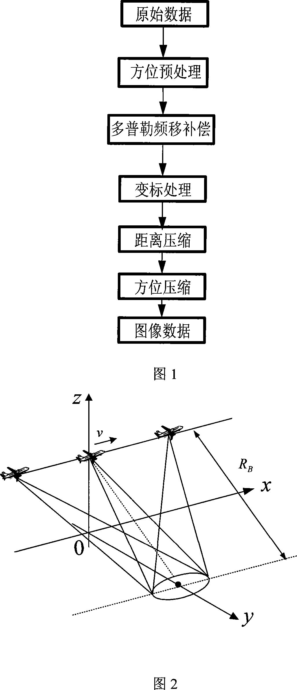
[0060] Referring to Figure 1, the specific process of the present invention is as follows:

[0061] 1. Preprocessing the original data of admission

[0062] Assuming that the lidar is to collect data according to the geometric relationship in Figure 2, since the azimuth preprocessing only solves the problem of azimuth spectrum aliasing, and does not achieve precise image focusing processing, we only need to consider the original data azimuth signal, the process is:

[0063] 1) The azimuth signal of the target in the original data can be expressed as:

[0064] s a = rect ( t m - t m , center T a ) · exp...


PUM


Abstract

The invention provides a beaming synthetic aperture radar laser imaging method, which is based on SAR imaging theory and based on the signal type difference between synthetic aperture laser radar SAL and synthetic aperture radar SAR to improve prior synthetic aperture radar SAR imaging method, to provide an imaging method suitable with synthetic aperture laser radar SAL. The inventive method comprises first processing direction pretreatment on the initial data prepared for imaging, processing Doppler frequency shift compensation on the data after pretreatment, processing point multiplication on the pretreated data and a structure phase factor exp(-j2f alpha), varying standard on the data after the Doppler frequency shift compensation, processing distance compression and direction compression on the data after the standard varying process, to obtain image data. The invention has the advantage of high image resolution, which is suitable for imaging small ground target.

Description

Technical field [0001] The invention belongs to the field of laser radar technology, and relates to target imaging, in particular to a spotlight synthetic aperture laser radar imaging method, which can be used for imaging ground targets and determining the size and shape of the target. Background technique [0002] Synthetic aperture processing technology mainly refers to synthetic aperture radar SAR imaging technology. Under ideal motion conditions, the imaging principle is relatively simple. Suppose there is a point target somewhere in the scene to be imaged, and its echo can be recorded in the two-dimensional plane of distance and azimuth. Through the pulse compression of the distance dimension, the recorded data is a complex curve in the distance-azimuth plane, called The system response of the target at this point. Then the system response function is constructed, and the position of each point target can be obtained through matched filtering, so as to reconstruct the image ...

Claims


Application Information

Patent Timeline
IPC IPC(8): G01S13/90
Inventor 邢孟道郭亮梁毅唐禹保铮
Owner XIDIAN UNIV
Learn More