
Vehicle relay and installation method of electronic components thereof

A technology of automotive relays and electronic components, applied in relays, electrical components, circuits, etc., can solve problems such as welding difficulties and virtual welding phenomena that cannot be effectively solved, hidden dangers of product reliability, and insufficient vibration resistance, and achieve good fixing effects. Improve product quality and finished product pass rate, use reliable and stable effect

Active Publication Date: 2008-07-23
NINGBO YINZHOU YONGLIN ELECTRON ELECTRICAL EQUIP
View PDF0 Cites 4 Cited by
  • Summary
  • Abstract
  • Description
  • Claims
  • Application Information

AI Technical Summary

Problems solved by technology

[0002] Automotive relays generally need to connect electronic components such as resistors, capacitors, or diodes between the coil lead sheets. Existing automotive relays use the method of directly welding electronic components such as resistors, capacitors, or diodes on the coil lead sheets. Defects such as virtual welding, insufficient vibration resistance at the welding place, and insufficient space for welding
In order to improve the product quality and meet the technical requirements of the product in various use environments, some technical measures have been taken to improve the product quality, such as adding a boss with a diameter similar to the lead end of the electronic component for welding at one end of the coil lead-out piece. This kind of welding is very difficult due to the small space of the welding part and the enameled wire of the coil, the plastic skeleton, the plastic base and other parts that cannot be burned during welding.
Another welding method is spot welding. The enameled wire of the coil winding is very thin, and the leading end must be twisted together in multiple strands. Spot welding with the leading end of the resistor will also cause virtual welding, so there are hidden dangers in the reliability of the obtained product. The virtual soldering phenomenon still cannot be effectively solved

Method used


Image

  • Vehicle relay and installation method of electronic components thereof
  • Vehicle relay and installation method of electronic components thereof
  • Vehicle relay and installation method of electronic components thereof

Examples


Embodiment Construction

[0013] The present invention will be further described in detail below in conjunction with the accompanying drawings and embodiments.

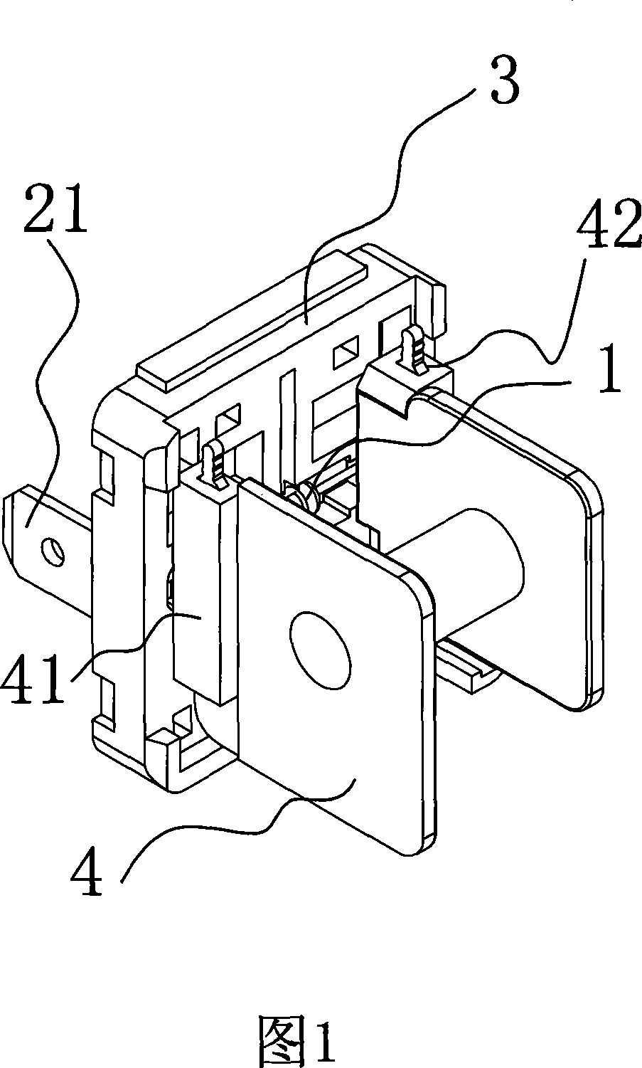
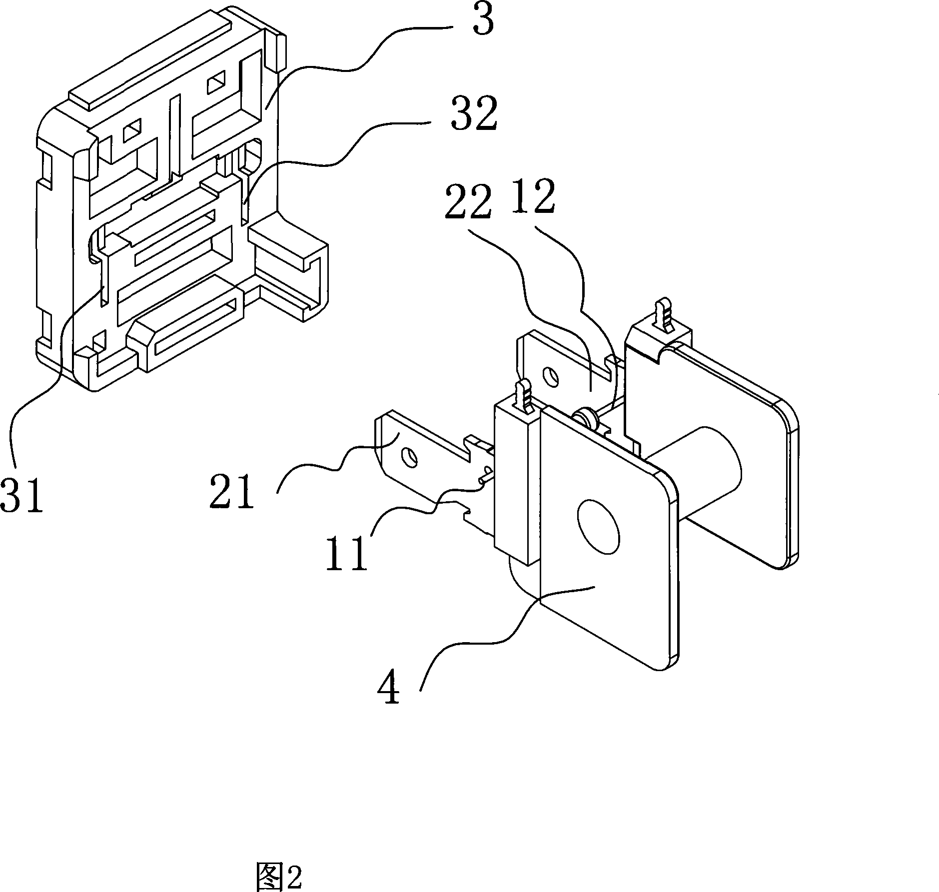
[0014] As shown in Fig. 1 and Fig. 2, the parts of the automotive relay involved in the present invention include a coil frame 4, a lead sheet 21, a lead sheet 22, an electronic component 1, a base 3, and the lead sheet 21 and the lead sheet 22 are inserted into the coil frame 4 Among the fixing pieces 41 and 42, the electronic component 1 is fixed on the lead piece 21 and the lead piece 22.

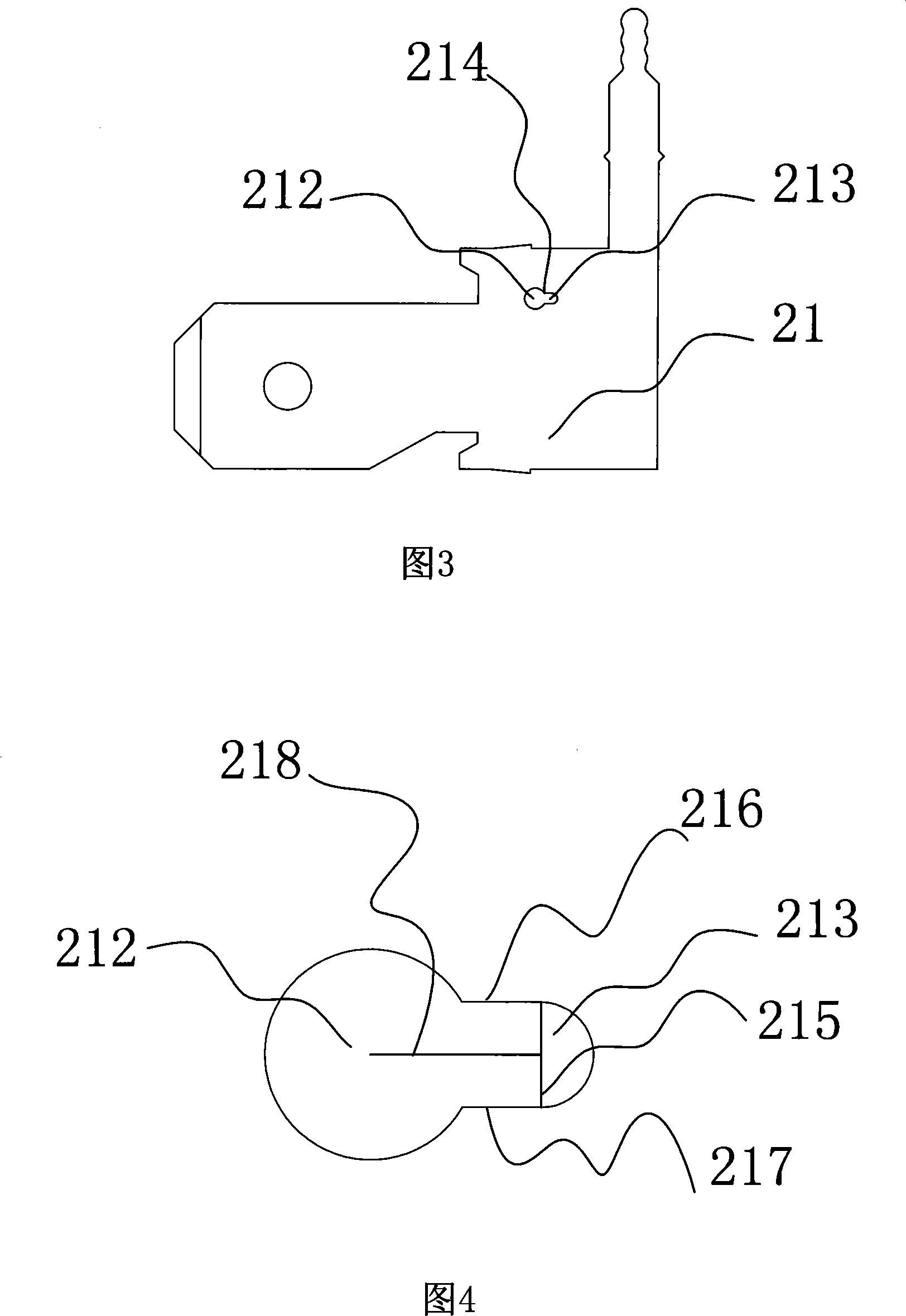
[0015] There is a hole 214 at the place where the above-mentioned lead piece 21 is installed with the electronic components, which is composed of a large hole 212 and a small hole 213 connected. To pass through it conveniently, a small hole 213 smaller than 20% of the diameter of the lead-out end of the electronic component is opened in front of the large hole 212, so that the lead-out end 11 is firmly embedded therein, as shown in FIG. 3 .

[0016] Abo...


PUM


Abstract

Disclosed is a car relay, which comprises a foundation, an electronic element, a pair of parallel coil lead chips, wherein the parallel coil lead chips are respectively inserted in a coil former, the lead chip is opened a hole which is larger than the diameter of the leading-out end of the electronic element, a hole smaller than the leading-out end of the electronic element is provided in the front of the hole, the two holes are connected mutually, the leading-out end of the electronic end is positioned in the bigger hole of the lead chip, the lead chip is inserted in the foundation, the leading-out end of the electronic element is inserted in the smaller hole from the bigger hole by the foundation. The invention additionally provides the corresponding installment method. The invention has the advantages of reasonable structural design, convenient installment and good fixing effect, which resolves problems of poor soldering in welding process of lead chips and difficult welding caused by small volume of relays and small installment space, greatly increases working efficiency, and the car relay can bear certain vibration, increase product quality and finished product percent of pass, and has reliable and stable usage and long service life.

Description

technical field [0001] The invention relates to an automobile relay, in particular to an automobile relay capable of conveniently connecting electronic components and an installation method thereof. Background technique [0002] Automotive relays generally need to connect electronic components such as resistors, capacitors or diodes between the coil lead pieces. Existing automotive relays use the method of directly welding electronic components such as resistors, capacitors or diodes on the coil lead pieces. Defects such as virtual welding, insufficient vibration resistance at the welding place, and insufficient space for welding. In order to improve the product quality and meet the technical requirements of the product in various use environments, some technical measures have been taken to improve the product quality, such as adding a boss with a diameter similar to the lead end of the electronic component at one end of the coil lead-out piece for welding, This welding is ...

Claims


Application Information

Patent Timeline
IPC IPC(8): H01H45/04H01H49/00
Inventor 王继伦王林沪钱和伟
Owner NINGBO YINZHOU YONGLIN ELECTRON ELECTRICAL EQUIP
Learn More