Intelligent power utilization system

An electric power system and intelligent technology, applied in electrical components, circuit devices, distribution substations, etc., can solve problems such as unmanned duty requirements, bus power loss, etc., to reduce fault handling time and operating costs, increase The effect of reliability

Inactive Publication Date: 2008-07-23
SUZHOU POWER SUPPLY OF JIANGSU ELECTRIC POWER +1
View PDF0 Cites 25 Cited by
  • Summary
  • Abstract
  • Description
  • Claims
  • Application Information

AI Technical Summary

Problems solved by technology

[0002] At present, the electrical system used in the substation uses two incoming line power supplies to supply power to the feeder circuit. The two incoming line power supplies are respectively electrically connected to the incoming line circuit breakers, the busbars electrically connected to each incoming line circuit breaker, and the two sections of busbars are electrically connected to each other. There are bus tie circuit breakers, and each circuit breaker has three working positions: opening, closing, and tripping. The system has multiple operating modes, one of which is that the two incoming line power sources are the main power supply, and the incoming line is open. The breakers are all in the closing position, the bus tie circuit breaker is in the opening position, and the main power supply supplies power to the corresponding busbars respectively; one operation mode is that one of the two incoming power supplies is the main power supply, and the other incoming power supply The incoming circuit breaker corresponding to the main power supply is in the closing position, the incoming circuit breaker corresponding to the standby power is in the opening position, and the bus tie circuit breaker is in the closing position, and the main power supply is in the two-section busbar Power supply at the same time. In the prior art, manual switching of each circuit breaker is mainly used to make the system operate in different operating modes. However, this manual mode cannot meet the requirements of unattended operation. Line power supply is the main power supply operation mode. When one line power supply loses power, this section of busbar will lose power, and the operating personnel must rush to the scene to deal with it in time to minimize the loss.

Method used


Image

  • Intelligent power utilization system

Examples


Embodiment Construction

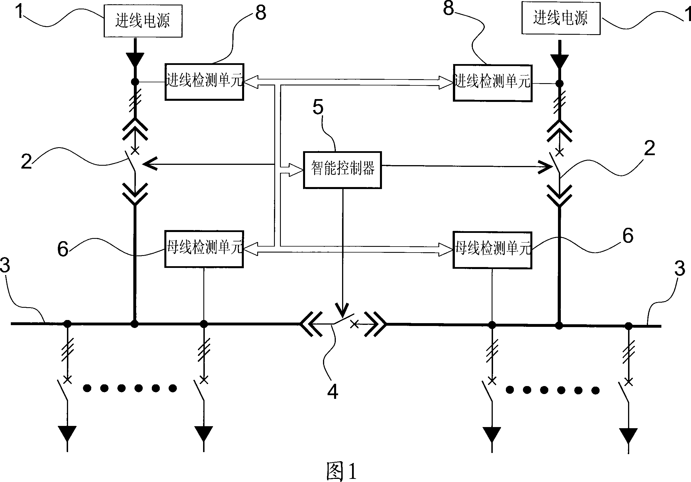
[0010] The specific embodiment of the present invention will be specifically introduced below in conjunction with accompanying drawing:

[0011] The intelligent power system shown in Figure 1 includes two incoming power sources 1, incoming circuit breakers 2 electrically connected to the two incoming power sources 1, and bus bars electrically connected to each incoming circuit breaker 2. 3. A bus-tie circuit breaker 4 is also connected between the two sections of busbar 3. To facilitate maintenance and replacement, each circuit breaker adopts a withdrawable circuit breaker, and the overcurrent protection value of each circuit breaker can be adjusted. Each circuit breaker has a separate There are three working positions of gate, close and short-circuit trip, so the system can operate in the following two modes: the first mode of operation is that the two incoming line power sources 1 are used as the main power supply respectively, and the two incoming line circuit breakers 2 are...


PUM


Abstract

The invention provides an intelligent employed electric system, which comprises a two-way incoming line power supply, an incoming line breaker which is respectively connected with the two-way incoming line power supply and a bus bar which is respectively and electrically connected with the incoming line power supply, wherein a bus coupling circuit breaker is electrically arranged between two sections of the bus bars, the invention also comprises an incoming line detecting unit, an intelligent controlling device which is electrically connected with each output end of the incoming line detecting unit, wherein the intelligent controlling device is also respectively and electrically connected with each breaker, the intelligent controlling device controls a close-open gate of each breaker through judging voltage and electric current value of each incoming line and according to the state of the current close-open gate of the breaker and the operating mode which is required by the system, the intelligent controlling device carries out an auto-switch-on control on each breaker according to the collected information when any incoming line power supply is failed, therefore the employed electric system can be led to continuously supply power, and the reliability of the employed electric system is effectively increased, failure processing time and operating cost are reduced, and the intelligent employed electric system is particularly applied on an unattended transformer station whose voltage grade is 110kV or under 110kV.

Description

technical field [0001] The invention relates to an electrical system used in a substation, in particular to an electrical system applied to a substation with a voltage level of 110kV or below. Background technique [0002] At present, the electrical system used in the substation uses two incoming line power supplies to supply power to the feeder circuit. The two incoming line power supplies are respectively electrically connected to the incoming line circuit breakers, the busbars electrically connected to each incoming line circuit breaker, and the two sections of busbars are electrically connected to each other. There are bus tie circuit breakers, and each circuit breaker has three working positions: opening, closing, and tripping. The system has multiple operating modes, one of which is that the two incoming line power sources are the main power supply, and the incoming line is open. The breakers are all in the closing position, the bus tie circuit breaker is in the openin...

Claims


Application Information

Patent Timeline
Patent Type & Authority Applications(China)
IPC IPC(8): H02J3/00H02J9/06H02B7/06H02B1/20
Inventor 冒烨颖李栋
Owner SUZHOU POWER SUPPLY OF JIANGSU ELECTRIC POWER
Why Eureka
Try Eureka