Thrust disc of release bearing of a disconnect clutch

A technology for release bearings and thrust plates, applied in clutches, mechanical drive clutches, mechanical equipment, etc., can solve problems such as low structural strength, short service life, and large wear, and achieve slipping suppression, easy operation, and self-determined acceleration heart effect

Inactive Publication Date: 2011-09-14
SCHAEFFLER TECH AG & CO KG
View PDF1 Cites 1 Cited by
  • Summary
  • Abstract
  • Description
  • Claims
  • Application Information

AI Technical Summary

Problems solved by technology

[0003] The disadvantage of the above-mentioned thrust plate is probably that its structural strength is small and its wear is high, which leads to its short service life
In addition, due to slippage between the face of the thrust plate facing away from the clutch and the annular engagement flange of a surrounding bearing ring of the release bearing, a lot of noise is generated

Method used


Image

  • Thrust disc of release bearing of a disconnect clutch
  • Thrust disc of release bearing of a disconnect clutch
  • Thrust disc of release bearing of a disconnect clutch

Examples


Embodiment Construction

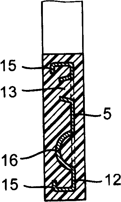
[0037] figure 1 Represent the longitudinal sectional view of thrust plate 1 of the present invention, corresponding to figure 2 A-A line in.

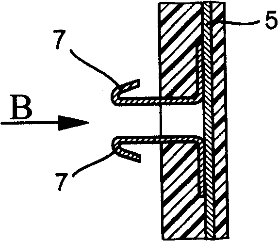
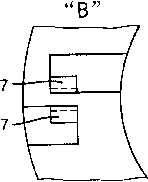
[0038] figure 2 means along figure 1 The view of the thrust plate 1 in the direction of the arrow "X", while Figure 1a is figure 1 Detail drawing of detail "Z".

[0039] The effect of the thrust plate 1 is to transmit the release force of the release bearing to the reed 2 of the disk spring of a shift release clutch. Neither the shift release clutch and the release bearing with disk springs are shown.

[0040]During disengagement and engagement, slippage occurs between the leaf reed 2 and a clutch-facing face 3 of the thrust disk 1 . Thus, the thrust plate wears on the contact surface of the reed 2. The contact surface is designed as a concavely curved circumferential groove 4 into which the end of the tongue 2 engages with a coaxial curvature.

[0041] Below the circumferential groove 4, there is a reinforcing rib 5, see al...


PUM


Abstract

The invention relates to a stop disc (1) of a release bearing of a disconnect clutch. The surface (10) of the disc lying furthest away from the clutch exerts a pressure on an annular flange of a continuous bearing ring of the release bearing and the surface (3) lying nearest to the clutch exerts pressure on the spring-loaded lugs (2) of a disc spring and is held in a positive fit by means of retaining arms (7) and struts (9) running radially between the spring-loaded lugs (2). The aim of the invention is to improve the structural and wear resistance, in addition to the mounting and noise levels of the stop disc (1) and to enable a rapid self-centring of the release bearing. To achieve this, the stop disc (1) comprises a reinforced section (5) and retaining arms (7) that preferably consistof metal and the plastic of the stop disc (1) has a reinforcing, friction-reducing fraction. The surface (10) that is furthest away from the clutch and the surface of the annular flange that is preferably coated with plastic are equipped with micro-structures that facilitate the rapid formation of a positive-fit connection between said two surfaces.

Description

technical field [0001] The invention relates to a release bearing of a shifting separation clutch, especially for automobiles with manual shifting or automatic shifting transmissions. Background technique [0002] In DE 34 24 227 a plastic-thrust plate of the release bearing of the shifting release clutch is described, the face of the thrust plate facing away from the clutch is in pressure contact with an annular engagement flange of a surrounding bearing ring of the release bearing, The clutch-facing side of the thrust disk is then in pressure contact with the leaves of a disk spring and is also positively locked via the arms and webs extending radially between the leaves. [0003] The disadvantage of the above-mentioned thrust plate is probably that its structural strength is small and its wear is high, which leads to its short service life. In addition, considerable noise is generated due to slipping between the face of the thrust plate facing away from the clutch and th...

Claims


Application Information

Patent Timeline
Patent Type & Authority Patents(China)
IPC IPC(8): F16D23/14
CPCF16D23/145F16D23/14
Inventor L·温克尔曼S·迪特默
Owner SCHAEFFLER TECH AG & CO KG
Why Eureka
Try Eureka