Ultra-sophisticated aerostatic motorized spindle system

A gas static pressure, electric spindle technology, which is applied to bearings, electromechanical devices, electrical components, etc., can solve the problems of inability to achieve direct drive, poor power transmission between the motor and the spindle, and poor rotation accuracy, and achieve simple structure and rotation. High degree and good dynamic characteristics

Inactive Publication Date: 2008-07-30
HARBIN INST OF TECH
View PDF0 Cites 38 Cited by
  • Summary
  • Abstract
  • Description
  • Claims
  • Application Information

AI Technical Summary

Problems solved by technology

[0003] The purpose of the present invention is to provide an ultra-precision gas static electric spindle system, which can solve the problem of poor rotation accuracy, inabi

Method used


Image

  • Ultra-sophisticated aerostatic motorized spindle system

Examples


specific Embodiment approach 1

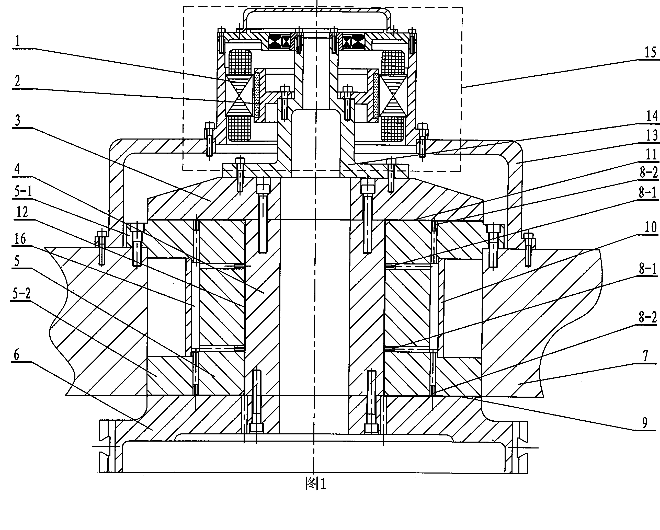
[0007] Specific embodiment 1: As shown in Figure 1, the ultra-precision gas static piezoelectric spindle system of this embodiment is composed of a DC brushless drive motor 15, a spindle 4, an upper thrust plate 3, a lower thrust plate 6, and a shaft sleeve 5. , The DC brushless drive motor 15 is located above the upper thrust plate 3, the motor shaft 14 on the DC brushless drive motor 15 is fixedly connected to the upper end surface of the upper thrust plate 3, and the main shaft 4 and the sleeve 5 are both located on the upper Between the thrust plate 3 and the lower thrust plate 6, the bushing 5 is sleeved on the main shaft 4. The lower end surface of the upper thrust plate 3 is fixedly connected with the upper end surface of the main shaft 4, and the lower end surface of the main shaft 4 is connected to the lower thrust plate 6 The upper end surface is fixedly connected, the motor shaft 14 is coaxial with the main shaft 4, and the sleeve 5 is provided with a plurality of radia...

specific Embodiment approach 2

[0009] Specific embodiment 2: As shown in Fig. 1, the upper end of the sleeve 5 of this embodiment is provided with an upper end boss 5-1, the lower end of the sleeve 5 is provided with a lower end boss 5-2, and the upper end boss 5-1 It is fixedly connected to the shafting bracket 7, and the lower end boss 5-2 is in contact with the inner wall of the shafting bracket 7. This design is easy to install. The other composition and connection relationship are the same as in the first embodiment.

specific Embodiment approach 3

[0010] Specific embodiment 3: As shown in FIG. 1, this embodiment further includes an air chamber sleeve 10, and the air chamber sleeve 10 is sleeved on the shaft sleeve 5. In this design, a closed air chamber 16 is formed between the air chamber sleeve 10 and the shaft sleeve 5 to improve the effect of the gas static pressure and the rotation accuracy of the main shaft. The other composition and connection relationship are the same as in the first embodiment.

[0011] working principle:

[0012] The stator 1 and the rotor 2 constitute a DC brushless drive motor 15. Since there is no brush, there is no frictional torque between the stator 1 and the rotor 2 of this motor, and a rotating torque can be directly generated to drive the spindle 4 to rotate and perform cutting. The upper thrust plate 3 and the lower thrust plate 6 of the aerostatic bearing are connected to the main shaft 4, and the length of the main shaft 4 and the height of the sleeve 5 are ground during manufacture to...


PUM


Abstract

The invention provides an ultraprecise aerostatic electric spindle system which relates to an electric spindle system. The invention solves the problems that in the spindle system of current ultraprecise processing devices, rotation accuracy is poor; direct drive can not be realized and transmission effects of the power of an electric motor and a spindle are unfavorable. A motor shaft (14) on a DC brushless drive motor (15) is fixedly connected with the upper end face of an upper thrust plate (3); the spindle (4) and a spindle sleeve (5) are positioned between the upper thrust plate (3) and a lower thrust plate (6); the spindle sleeve (5) is sleeved on the spindle (4); the lower end face of the upper thrust plate (3) is fixedly connected with the upper end face of the spindle (4); the lower end face of the spindle (4) is fixedly connected with the upper end face of the lower thrust plate (6). The motor shaft (14) and the spindle (4) are coaxial; the spindle sleeve (5) is opened with a plurality of radial restriction orifices (8-1) and a plurality of axial restriction orifices (8-2). In the invention, an aerostatic bearing is used as an axial support and a radial support, which guarantees the rotation accuracy of the spindle; the aerostatic bearing has the effect for homogenizing the geometric accuracy of the spindle and the spindle sleeve so that shafting has extremely high rotation accuracy.

Description

Technical field [0001] The invention relates to an electric spindle system. Background technique [0002] With the development of science and technology, the requirements for the manufacturing accuracy of product parts are getting higher and higher. There is an urgent need for ultra-precision machining equipment and technology, especially ultra-precision machining machine tools, which are the core and key of the field of ultra-precision machining technology. In the ultra-precision machining machine tool, the spindle system is a key component, and its accuracy directly affects the machining accuracy of the parts. Therefore, how to design and manufacture ultra-precision spindles has become the core and key of ultra-precision machining machine tools. As far as ultra-precision machining machine tools are concerned, the design of the spindle mainly considers two aspects: one is the problem of spindle rotation accuracy, and the other is the problem of drive structure and mode, because ...

Claims


Application Information

Patent Timeline
IPC IPC(8): B23B19/02B23Q5/04F16C32/06H02K7/08
Inventor 梁迎春张飞虎张龙江陈明君许乔
Owner HARBIN INST OF TECH
Why Eureka
Try Eureka