
Rotary display panel detection device

A display panel and detection device technology, which is applied in the direction of measuring devices, optical instrument testing, optical performance testing, etc., can solve the problems of long detection cycle, restricting the production of display panels, time-consuming and labor-consuming, etc., and achieves easy maintenance, up-down connection The effect of easy and quick adjustment and shortened production cycle

Pending Publication Date: 2019-04-12
WUHAN JINGLI ELECTRONICS TECH +1
View PDF5 Cites 7 Cited by
  • Summary
  • Abstract
  • Description
  • Claims
  • Application Information

AI Technical Summary

Problems solved by technology

[0003] In the existing production process, when testing multiple different processes of the display panel, it is often necessary to design a number of different equipment in combination with the actual situation to complete it together, which requires continuous loading and unloading, which is not only time-consuming and labor-intensive, but also The long cycle severely restricts the production of display panels

Method used


Image

  • Rotary display panel detection device
  • Rotary display panel detection device
  • Rotary display panel detection device

Examples


Embodiment Construction

[0019] The present invention will be further described below in conjunction with the accompanying drawings and specific embodiments.

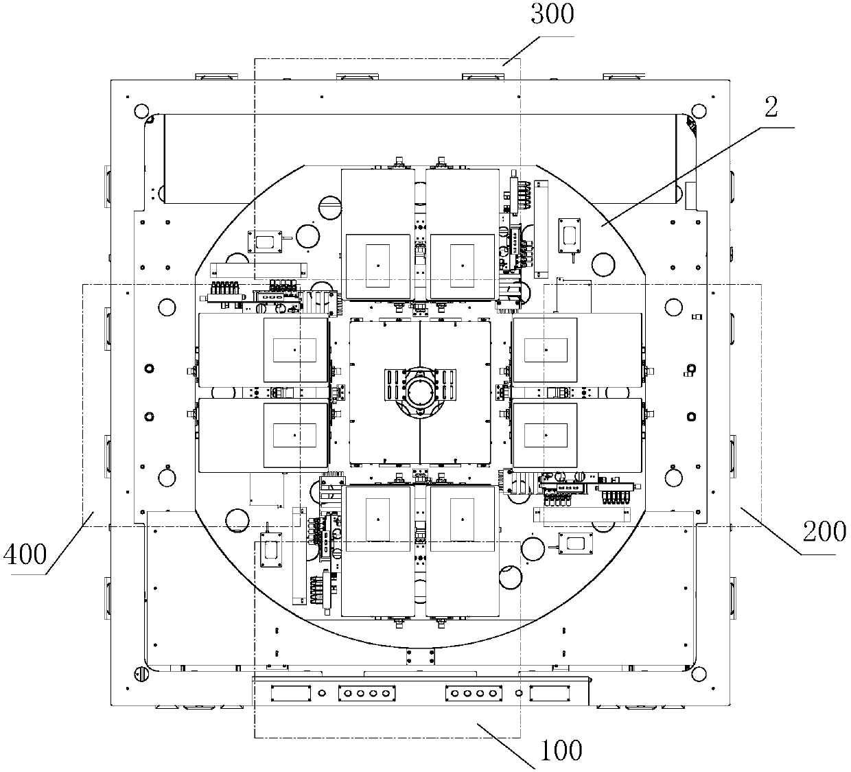
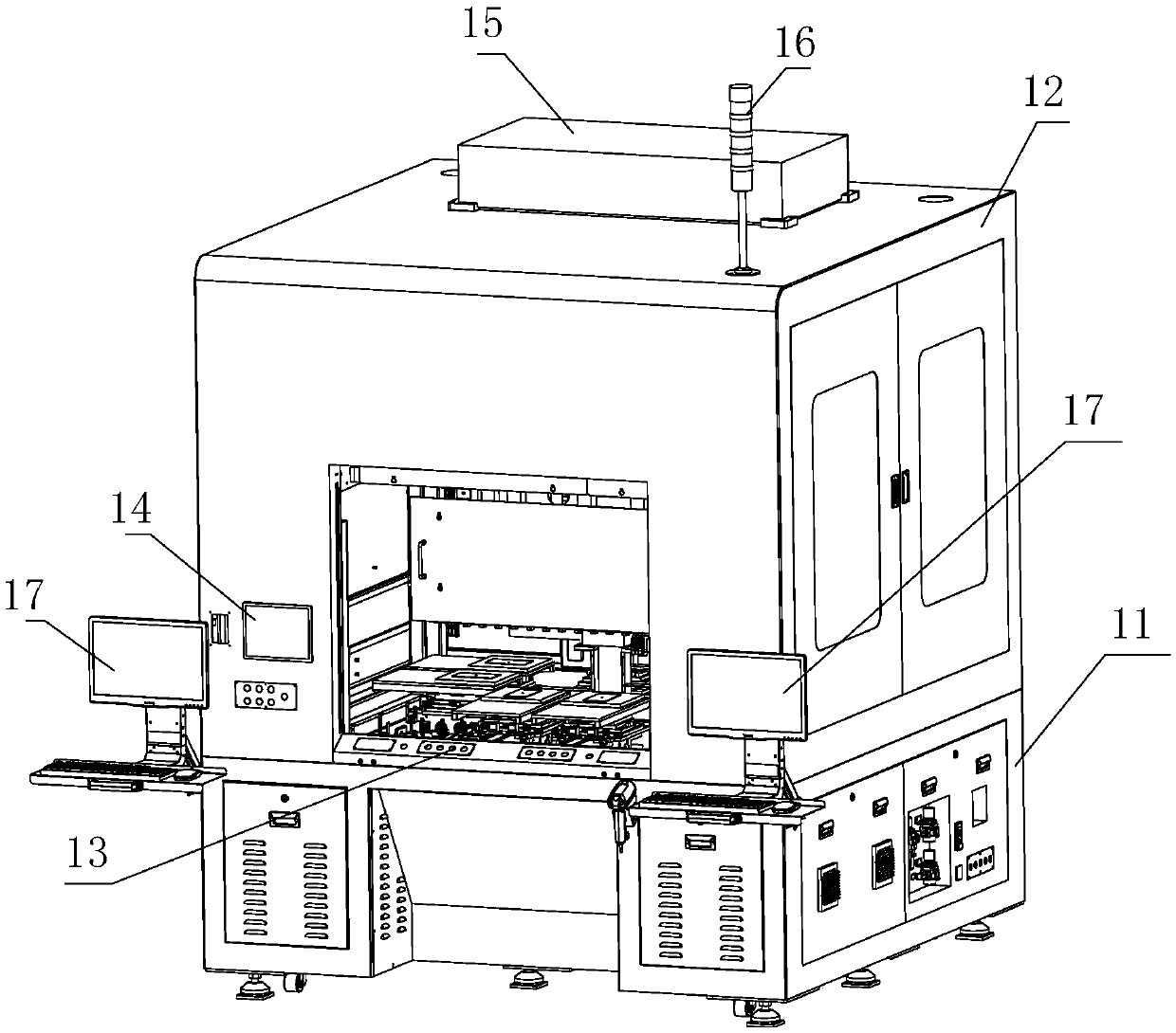
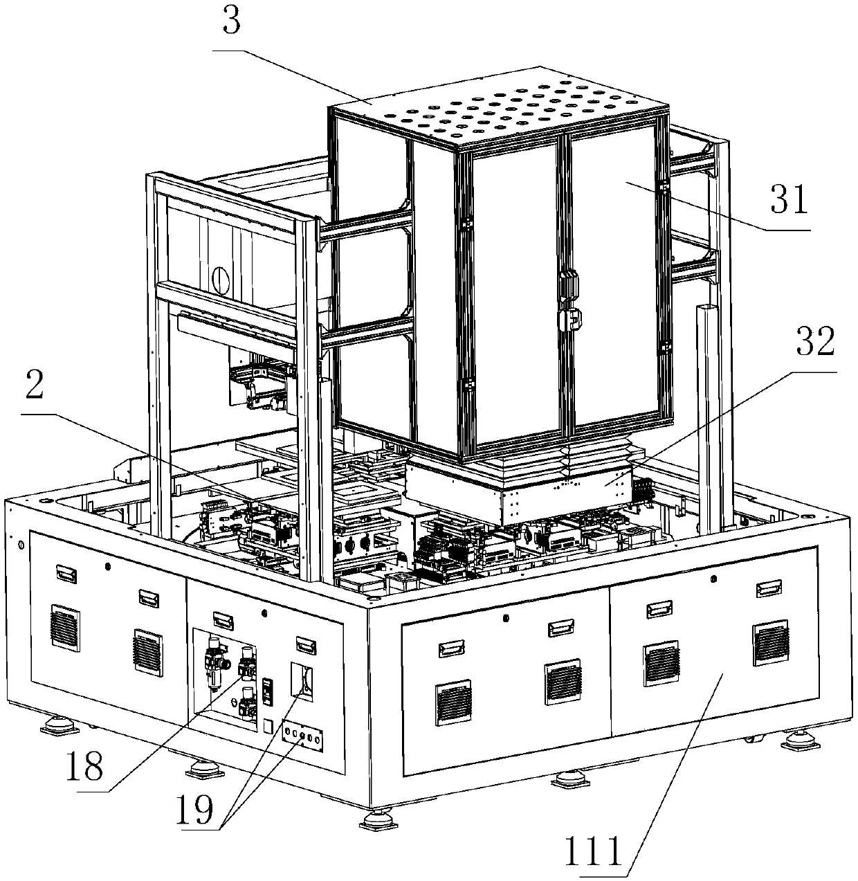
[0020] Such as figure 1 As shown, a rotary display panel detection device of the present invention includes a turntable assembly 2 and an optical-mechanical assembly 3, and four stations are arranged at corresponding positions in the four directions of the turntable assembly 2, which are respectively: a loading and unloading station 100, a wiping station In addition to the station 200, the camera photo inspection station 300 and the burning rejudgment station 400, the upper end surface of the turntable 20 of the turntable assembly 2 is evenly provided with a number of jigs 6, and the several jigs 6 correspond to the positions of the four stations. 2 rotates, the display panel on the jig 6 of the turntable assembly 2 passes through four stations in sequence, and when the turntable assembly 2 rotates to the corresponding station, the correspondin...


PUM


Abstract

The invention relates to a rotary display panel detection device. The rotary display panel detection device comprises a rotating disc assembly and an optical-mechanical assembly. Four stations are arranged at positions corresponding to the four directions of the rotating disc assembly; the rotating disc assembly rotates; display panels on rotating disc jigs sequentially penetrate through the fourstations to complete operations on the corresponding stations; and an operator can complete feeding and discharging, erasing, camera photographing detection and burning re-judgment on one of the stations through a set of equipment, so that the production cycle of the display panels is greatly shortened. A cam divider and a four-index inductor are arranged at the bottom of a rotating disc to ensurethe rotating precision of the rotating disc. An outer cover is provided with a safety door lock, a safety grating, a man-machine interface, an operation window and the like, and doors and windows arearranged on the upper and lower peripheries to facilitate maintenance. The optical-mechanical assembly is composed of two sets of optical-mechanical modules, linkage servo modules are arranged, and an optical-mechanical part is provided with a quick-disassembling type darkroom, so that simple and quick up and down joint debugging on an optical machine is achieved.

Description

technical field [0001] The invention relates to the field of display panel testing, in particular to a rotating display panel testing device. Background technique [0002] With the rapid development of display panels, the demand for panel inspection devices in the market is increasing day by day, and many display panel inspection devices are gradually going into mass production. At present, multi-station and multi-station devices are mostly used in the industry to realize offlinedemura, gamma, AOI and other detections. During the detection process, it is often necessary to complete multiple different processes. [0003] In the existing production process, when testing multiple different processes of the display panel, it is often necessary to design a number of different equipment in combination with the actual situation to complete it together, which requires continuous loading and unloading, which is not only time-consuming and labor-intensive, but also The long cycle sev...

Claims


Application Information

Patent Timeline
Patent Type & Authority Applications(China)
IPC IPC(8): G01M11/02
CPCG01M11/00
Inventor 周小培罗军郭洋
Owner WUHAN JINGLI ELECTRONICS TECH
Learn More