Method for reducing integer energy consumption of colour dyeing machine in dyeing and finishing manufactory

A technology of energy consumption and energy consumption, applied in the direction of computer control, instruments, simulators, etc., can solve the problems of different reproducibility of dyeing processing, machine delays, increased energy consumption, etc., to improve energy supply equipment and ensure factory Benefits, the effect of improving factory efficiency

Inactive Publication Date: 2008-07-30
巫协森
View PDF0 Cites 3 Cited by
  • Summary
  • Abstract
  • Description
  • Claims
  • Application Information

AI Technical Summary

Problems solved by technology

[0005] (1). The water inflow is slow for 10 minutes. It is not only one delay, but a large number of equipment delays. Therefore, most of the processing procedures are delayed, and the energy consumed is calculated in multiples.
[0006] (2). The slow temperature rise is caused by insufficient steam, which will relatively cause the delay of most dyeing machines, and simultaneously increase the extra energy demand, which will increase the energy consumption instead.
[0008] (4).Due to insufficient cooling water when cooling down, the loss of the main pump for 10 minutes is caused
[0009] (5). Due to the inability to accurately match the energy demand in the process, the delay of the machine caused by the work will make the reproducibility of the dyeing process different, and indirectly make the quality control effect relatively poor.
[0010] From the above-mentioned deficiencies, i

Method used


Image

  • Method for reducing integer energy consumption of colour dyeing machine in dyeing and finishing manufactory
  • Method for reducing integer energy consumption of colour dyeing machine in dyeing and finishing manufactory
  • Method for reducing integer energy consumption of colour dyeing machine in dyeing and finishing manufactory

Examples


Embodiment Construction

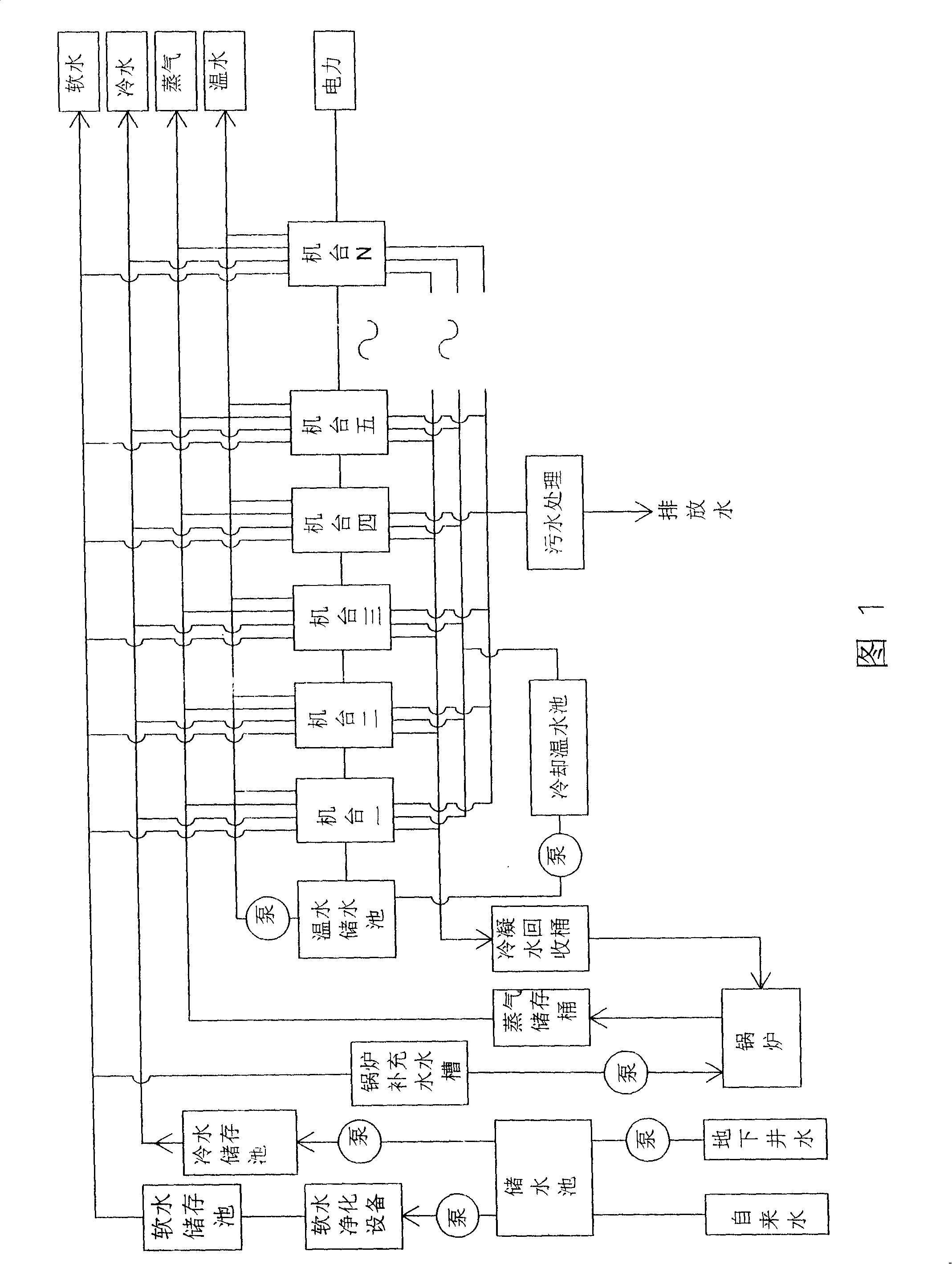
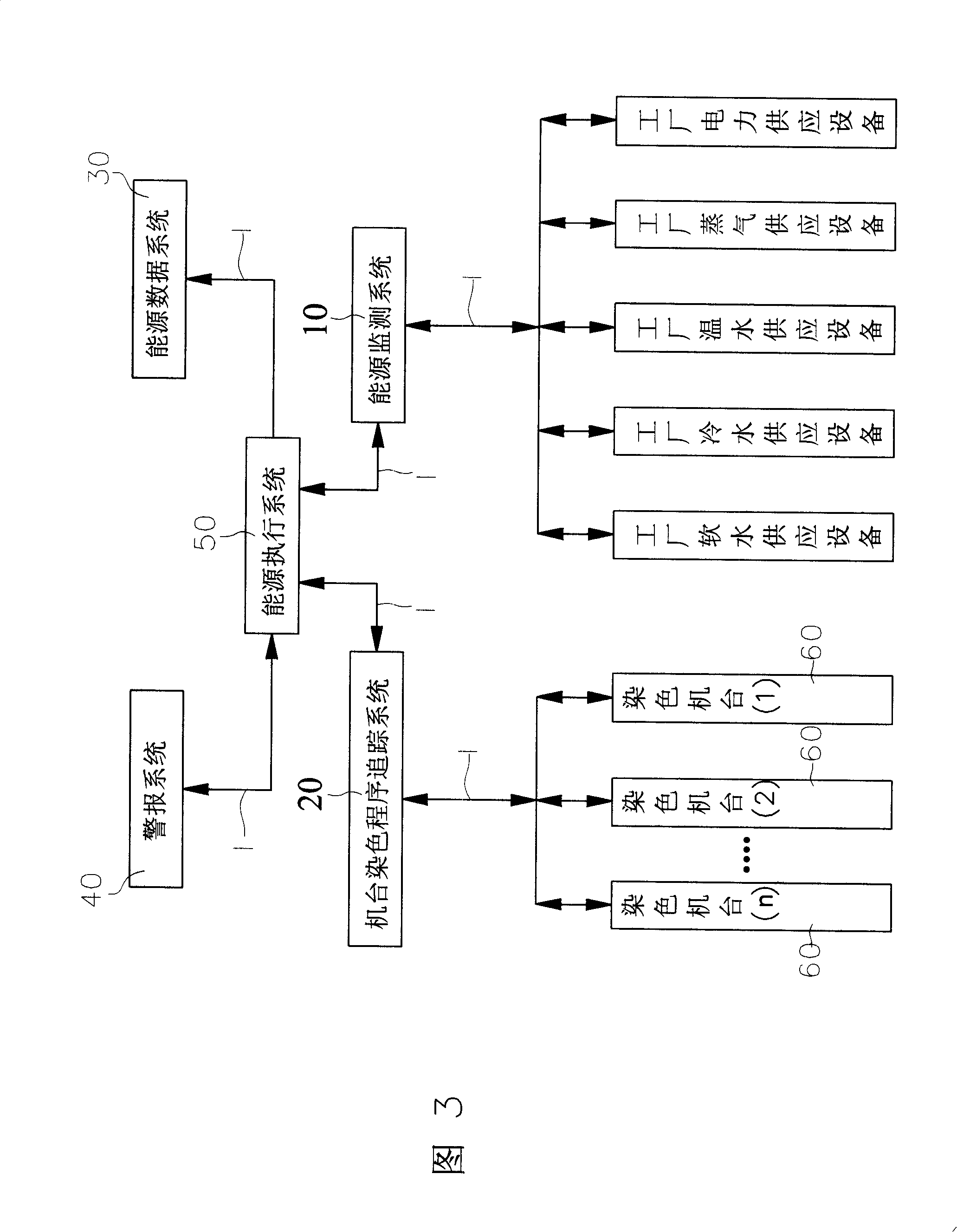
[0049] Please refer to Figure 3 and shown in Figure 1, the present invention provides a method for reducing the overall energy consumption of dyeing machines in dyeing and finishing factories, which includes: an energy monitoring system 10, a machine dyeing program tracking system 20, and an energy data system 30. Alarm system 40 and energy execution system 50; wherein,

[0050] The energy monitoring system 10 is composed of various detectors (sensors) installed on each energy supply equipment of the factory and its transmission pipelines and storage equipment, and communicates with the energy execution system through the local area network 1 in the factory. 50 phase connection, through the various detectors, the data of all energy sources including power supply, steam supply, warm water supply, cold water supply and soft water supply in the dyeing and finishing factory can be monitored at any time, and the heat of the various energy sources , pressure, temperature, flow, stor...


PUM


Abstract

A method for reducing the total energy consumption of dyeing machines in a dyeing/finishing plant is provided. The method involves an energy monitoring system, a dyeing program tracing system, an energy data system, an alarm system and an energy execution system. The energy monitoring system comprises a plurality of detectors. The dyeing program tracing system is connected with the dyeing machines in the dyeing/finishing plant. The energy data system is preset with energy supply capacity response curve data, energy need data and response curve data of the dyeing/finishing plant. The alarm system can provide alarm signals when detecting abnormality in energy consumption of all the dyeing machines. The energy execution system comprises a central control computing and is connected with the energy monitoring system, the dyeing program tracing system, the energy data system and the alarm system via a local network in the dyeing/finishing plant. The energy execution system has the production modes for reception and transfer of data of each system, real-time analysis of energy consumption data of the plant and execution of optimal energy utilization, thereby minimizing the energy consumption.

Description

【Technical field】 [0001] In the present invention, the energy consumption data of all dyeing machines in the dyeing and finishing factory are received, calculated and analyzed by the energy execution system constituted by the central control computer, and then the best energy-saving production mode is adjusted accordingly. And then achieve the goal of reducing the energy consumption of the overall dyeing and finishing factory. 【Background technique】 [0002] At present, the dyeing machines used in all dyeing and finishing factories are provided by the manufacturers of dyeing machine equipment, and the dyeing machine manufacturers will only improve the performance of a single dyeing machine as their main research and development improvement goal , such as: how to reduce bath ratio dyeing, how to apply advanced controllers to improve the reproducibility of dyeing, etc. Therefore, the problem of energy matching generated by various production conditions in the dyeing and finish...

Claims


Application Information

Patent Timeline
IPC IPC(8): G05B19/048
Inventor 巫协森
Owner 巫协森
Why Eureka
Try Eureka