
Circular polarization aerial

A polarized antenna, circular technology, applied in the field of global satellite positioning system, can solve the problem of not conforming to the radiation direction

Inactive Publication Date: 2011-08-10
连展科技电子(昆山)有限公司
View PDF0 Cites 0 Cited by
  • Summary
  • Abstract
  • Description
  • Claims
  • Application Information

AI Technical Summary

Problems solved by technology

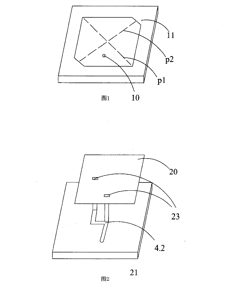
[0004] Although the above two antenna designs can achieve the effect of circular polarization, the main radiation direction of the circular polarization is perpendicular to the ground plane of the antenna. In the upright state, that is, the ground plane of the system is vertical to the ground and points to the sky. Therefore, if the application is to be embedded in general handheld wireless communication devices (such as mobile phones and PDAs), the circular polarization radiation direction generated by the antenna will The direction parallel to the system ground plane should be more suitable. The above two designs do not meet the required radiation direction in use.

Method used


Image

  • Circular polarization aerial
  • Circular polarization aerial
  • Circular polarization aerial

Examples


Embodiment Construction

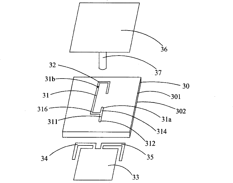
[0015] image 3 Shown is the first embodiment of the circularly polarized antenna of the present invention, which includes: a dielectric substrate 30, the dielectric substrate 30 has a first surface 301 and a second surface 302, and the dielectric substrate 30 can be a microwave dielectric Material; a feeding network 31, located on the first surface 301 of the dielectric substrate 30, comprising: a central conductor 311, the central conductor 311 has an initial end and an end, a feed-in point 312, located on the central conductor 311 The starting end, a first signal point 31a, a shorter branch wire 314, one end point is connected with the end of the central wire 311, the other end is connected with the first signal point 31a, a second signal point 31b, a Longer branch wire 316, one end of which is connected to the end of the central wire 311, and the other end is connected to the second signal point 31b, wherein the central wire 311, the shorter branch wire 314 and the longer ...


PUM


Abstract

The invention relates to a circular polarized antenna, which comprises a radiation conductor, a copper pillar, a feed-in network, a coupling wire, a grounding surface, a first extending wire, a second extending wire, a dielectric substrate and a feed-in wire. The coupling wire is coupled with the first extending wire and the second extending wire to excite a linearly polarized radiation characteristic. The radiation conductor is connected with the copper pillar to excite another linearly polarized radiation characteristic. Accordingly, two linearly polarized radiation characteristics in the vertical polarization direction, and the two linear antennas are integrated together through the feed-in network. The antenna is of good circular polarization characteristics by adjusting the feed-in network.

Description

technical field [0001] The present invention relates to a circular polarization antenna, especially an antenna used in wireless communication products, including the Global Positioning System (GPS). Background technique [0002] With the rapid development of wireless communication in recent years, the demand for antennas in various wireless communication products has gradually increased. Among them, the application of the Global Positioning System (GPS) has gradually changed from the original military-only to civilians. For use, the microwave signal of the satellite must be able to pass through the ionosphere in the atmosphere smoothly during transmission. At this time, only the signal with circular polarization characteristics can transmit the signal smoothly without being affected by the ionosphere in the atmosphere. In addition, the circular polarization Polarization can effectively improve the ability of general linear antennas to suppress multipath interference, so circ...

Claims


Application Information

Patent Timeline
Patent Type & Authority Patents(China)
IPC IPC(8): H01Q1/36H01Q1/38H01Q9/30H01Q13/00H01Q21/24
Inventor 林孝承萧智仁邱宗文萧富仁
Owner 连展科技电子(昆山)有限公司
Learn More