Piping with fluid mixing region

A fluid mixing and piping technology, used in fluid mixers, mixers, gas/liquid distribution and storage, etc., can solve the problem of difficult to completely prevent temperature interface changes, prevent thermal fatigue, promote mixing, reduce The effect of temperature changes

Inactive Publication Date: 2008-07-30
MITSUBISHI HEAVY IND LTD
View PDF1 Cites 5 Cited by
  • Summary
  • Abstract
  • Description
  • Claims
  • Application Information

AI Technical Summary

Problems solved by technology

[0006] However, according to the technology described in Patent Document 1, although fluid mixing can be promoted, it is difficult to completely prevent fluctuations in the temperature interface that occurs at various parts of the piping.

Method used


Image

  • Piping with fluid mixing region
  • Piping with fluid mixing region
  • Piping with fluid mixing region

Examples


no. 1 approach

[0074] Next, a first embodiment of the present invention will be described with reference to FIG. 1 .

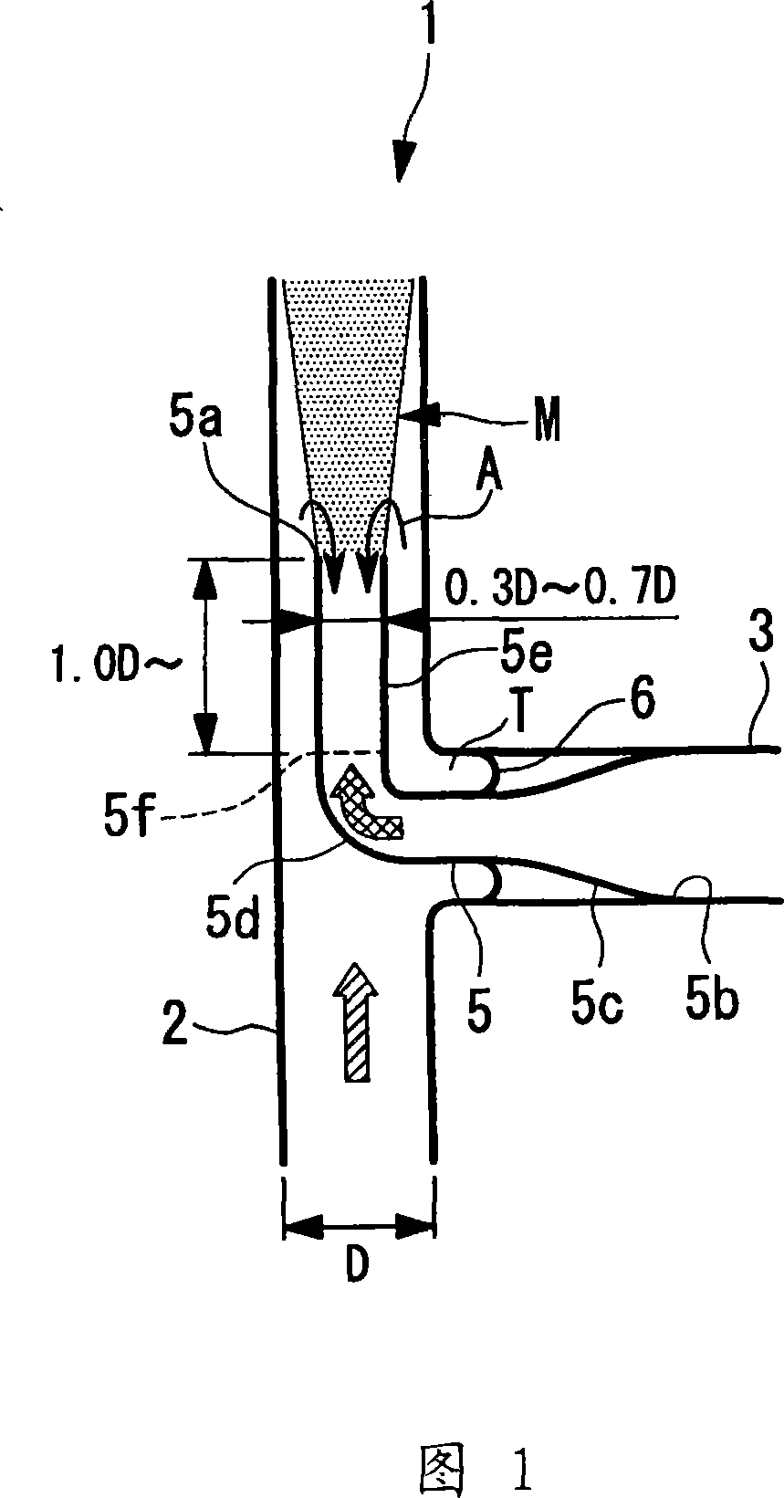
[0075] FIG. 1 shows a pipe 1 having a fluid mixing region M. As shown in FIG.

[0076] The pipe 1 is composed of a main pipe (first pipe) 2 and a branch pipe (second pipe) 3 .

[0077] The main pipe 2 is made of metal with an inner diameter D, and high-temperature water (high-temperature fluid) flows from the bottom to the top in this figure.

[0078] The branch pipes 3 are connected in an orthogonal manner with respect to the outer wall of the main pipe 2 . The branch pipe 3 is made of metal, and low-temperature water (low-temperature fluid) having a temperature lower than that of the high-temperature water flowing through the main pipe 2 flows therein. The low-temperature water flowing in the branch pipe 3 flows from the right side to the left side in the drawing, passes through the reducer (inner pipe) 5 , and flows out into the main pipe 2 from the downstream end 5 a o...

no. 2 approach

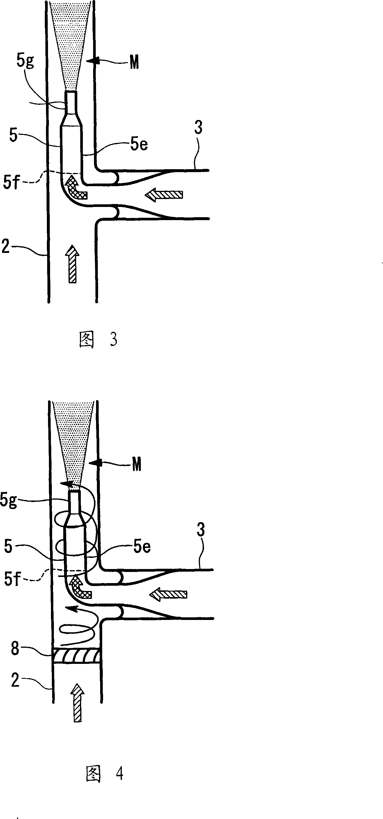
[0098] Next, a second embodiment of the present invention will be described with reference to FIG. 3 .

[0099] The difference between this embodiment and the first embodiment is that a diameter-reducing portion 5g is provided at the front end portion 5e of the reducer 5, and the rest is the same as that of the first embodiment. Therefore, descriptions of the same structures are omitted.

[0100] As shown in FIG. 3 , on the downstream end side of the front end portion 5 e of the reducer 5 , a reduced diameter portion 5 g having an inner diameter smaller than that on the upstream side is provided. Therefore, the low-temperature water flowing in the branch pipe 3 and introduced into the reducer 5 is further accelerated at the reduced diameter portion 5g. Therefore, the high-temperature water flowing outside the reducer 5 can be prevented from flowing backward into the reducer 5 . Thereby, since the temperature interface does not reach the inside of the reducer 5, the welding w...

no. 3 approach

[0104] Next, a third embodiment of the present invention will be described with reference to FIG. 5 .

[0105] The difference between this embodiment and the first embodiment is that an inner cylinder 10 is provided at the front end of the reducer 5 , and the other aspects are the same. Therefore, descriptions of the same structures are omitted.

[0106] As shown in FIG. 5 , the inner cylinder 10 is inserted into the inside of the front end portion 5 e of the reducer 5 . The downstream end 10a of the inner cylinder 10 is arranged on the downstream side of the downstream end 5a of the reducer 5 . A gap having an annular cross section is formed between the outer peripheral wall of the inner cylinder 10 and the inner peripheral wall of the front end portion 5e of the reducer 5 .

[0107] According to this embodiment, since the inner cylinder 10 is provided inside the reducer 5, and a gap is formed between the inner peripheral wall of the reducer 5 and the outer peripheral wall ...


PUM


Abstract

The present invention provides a pipe having a fluid mixing region where fluids of different temperatures are mixed, and an object of the present invention is to prevent thermal fatigue caused by fluctuations in the temperature interface. The pipe (1) of the present invention has a reducer (5) whose front end (5e) is arranged substantially on the central axis of the main pipe (2) and through which low-temperature water flows. The flowing high-temperature water has different temperatures, and the flow velocity is smaller than that of high-temperature water, and there is a fluid mixing area (M) for mixing high-temperature water and low-temperature water on the downstream side of the reducer (5). (5) A welded part (5f) connecting the front end part (5e) and the elbow part (5d) is formed on the top, and the distance between the welded part (5f) and the downstream end (5a) is the inner diameter (D) of the main pipe (2) above.

Description

technical field [0001] The present invention relates to a pipe suitable for use in, for example, a nuclear power plant or the like, and having a fluid mixing region for mixing fluids of different temperatures. Background technique [0002] For example, in power plants such as nuclear power plants and thermal power plants, many pipes through which high-temperature water or low-temperature water flow are installed. These pipes are connected to the branch pipes in a manner perpendicular to the main pipe, and there is a fluid mixing area where the low-temperature water flowing through the branch pipes and the high-temperature water flowing through the main pipe converge (of course, it can also be that the low-temperature water flows in the main pipe and the high-temperature water flows in the branch pipes. fluid structure). In such a fluid mixing region, a temperature interface is formed between high-temperature water and low-temperature water, and there is a problem that the m...

Claims


Application Information

Patent Timeline
Patent Type & Authority Applications(China)
IPC IPC(8): F16L55/00B01F5/00B01F5/02F17D1/17
CPCB01F2025/913B01F25/313
Inventor 近藤喜之谷本浩一铃木盛喜新田义一莲沼俊胜
Owner MITSUBISHI HEAVY IND LTD
Why Eureka
Try Eureka