

Imaging optical system
A technology of imaging optics and optical surfaces, applied in optics, optical components, lenses, etc., can solve problems such as difficult processing and difficulty in realizing automated mass production rates
- Summary
- Abstract
- Description
- Claims
- Application Information
AI Technical Summary
Problems solved by technology
Method used
Image

Examples
Embodiment 1
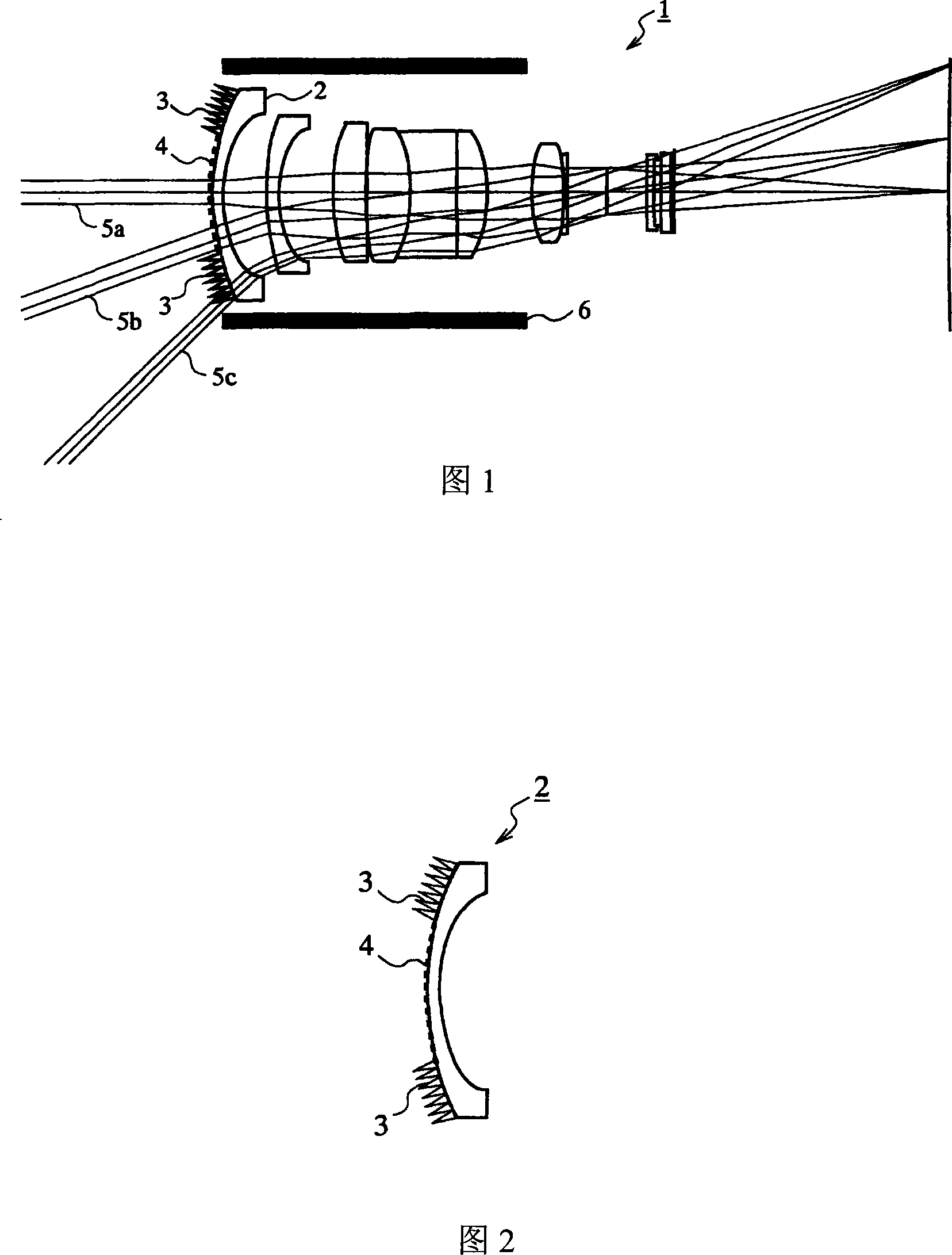
[0047] FIG. 1 is a schematic sectional view showing the structure of an imaging optical system 1 according to Embodiment 1. As shown in FIG. Figure 1 shows an example of an imaging optical system suitable for wide-angle image capture with constant focal length. The imaging optical system 1 is held by a lens barrel 6 . The light beams 5 a , 5 b , 5 c are light beams passing through the imaging optical system 1 . The light beam 5 c is a light beam passing through at the maximum viewing angle of the imaging optical system 1 .
[0048] FIG. 2 is an enlarged view of the lens element 2 located on the most object side among the lens elements employed in the imaging optical system 1 shown in FIG. 1 . In FIG. 2 , the lens element 2 is at least a part of a peripheral region (hereinafter simply referred to as a “peripheral region”) around a central region (hereinafter simply referred to as a “central region”) including the center (near the center) of the object-side optical surface. w...
Embodiment 2
[0097] In Example 1, an antireflection multilayer film was formed in the central region of the lens element located on the most object side, while an antireflection structure was formed in the peripheral region. Here, an antireflection multilayer film may be formed to cover the entire surface of the lens element, and then an antireflection structure is formed thereon.
[0098] The basic structure of the imaging optical system according to the present Embodiment 2 is similar to that of the imaging optical system according to Embodiment 1. In this way, reference is made to the structure of the imaging optical system of FIG. 1 . Here, the lens element 2 in FIG. 1 is replaced by the lens element 12 shown in FIG. 10 in this Embodiment 2. As shown in FIG.
[0099] FIG. 10 is an enlarged view of the lens element 12 employed in the imaging optical system according to Embodiment 2. As shown in FIG. In FIG. 10 , the antireflection multilayer film 14 is formed to cover the entire surfa...
Embodiment 3
[0103] The basic structure of the imaging optical system according to the present Embodiment 3 is similar to that of the imaging optical system according to Embodiment 1. However, in the lens element located on the most object side, the configuration of the antireflection structure provided in at least a part of the peripheral region of the object side optical surface is different from that in Embodiment 1.
[0104] 11 is a partially enlarged sectional view of the lens element 22 employed in the imaging optical system according to Embodiment 3. As shown in FIG. The lens element 22 corresponds to the lens element 2 shown in FIG. 1 , and is a lens element located on the most object side of the imaging optical system 1 of FIG. 1 . As shown in FIG. 11 , a sheet 25 having an antireflection structure 23 is adhered in at least a part of the peripheral region of the substrate 24 constituting the lens element 22 and is composed of, for example, a material capable of absorbing incident ...
PUM
| Property | Measurement | Unit |
|---|---|---|
| height | aaaaa | aaaaa |
Abstract
Description
Claims
Application Information