Rotating current hydrogen oxygen generator

A technology of rotating water flow, hydrogen and oxygen, applied in the direction of cells, electrolysis process, electrolysis components, etc., can solve the problems of increased power consumption, easy tempering, low gas output, etc., and achieve the effect of reducing power consumption

Inactive Publication Date: 2008-08-06
安士英
View PDF0 Cites 7 Cited by
  • Summary
  • Abstract
  • Description
  • Claims
  • Application Information

AI Technical Summary

Problems solved by technology

[0002] The current hydrogen-oxygen gas engine is mainly composed of an electrolytic cell, cathode and anode, heat-resistant insulating pipe, electrolyte, water-gas separator, hydrogen-oxygen gas outlet, safety valve, spray head, cooling water inlet, and cooling water outlet. There are the following Defects: 1. The electrolytic cell is prone to heat, which hinders water electrolysis and increases power consumption; 2. The electrolyte water chan...

Method used


Image

  • Rotating current hydrogen oxygen generator
  • Rotating current hydrogen oxygen generator

Examples


Embodiment Construction

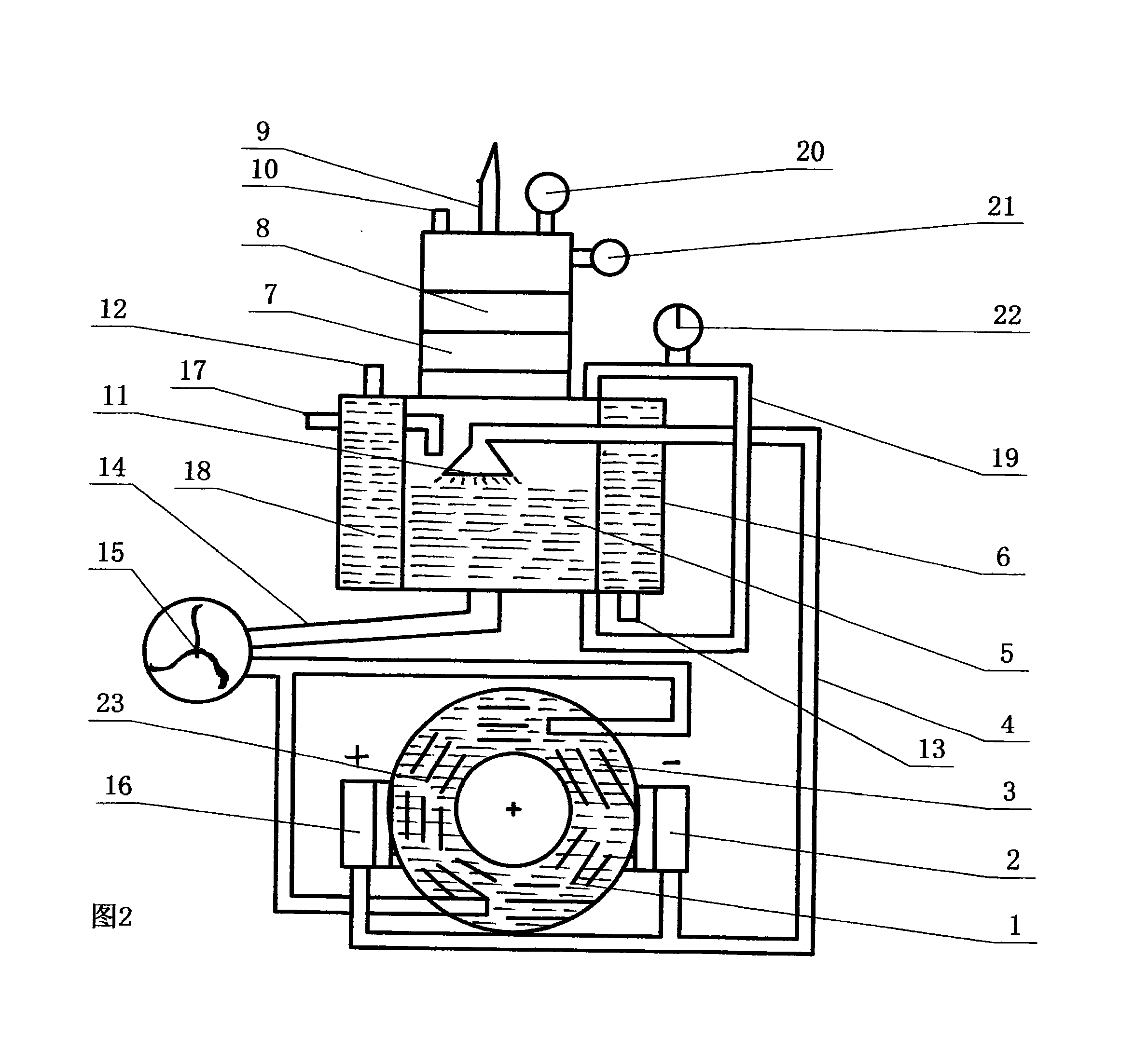
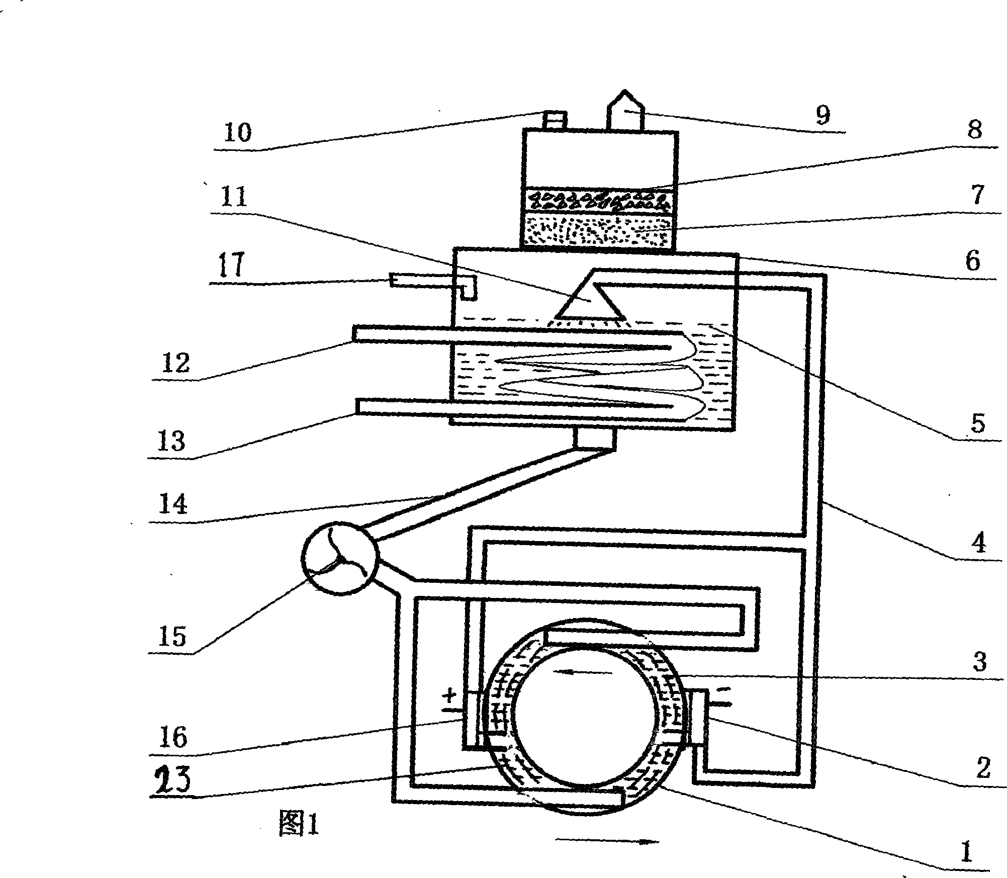
[0010] The embodiments are further described below in conjunction with the accompanying drawings.

[0011] Referring to Figure 1 and Figure 2, 1-electrolyzer, 2, cathode, 3-electrolyte, 4-heat-resistant insulating pipe, 5-cooling water, 6-water and gas separator, 7-sponge filter layer, 8-stainless steel Chip filter layer, 9-hydrogen oxygen outlet, 10-safety valve, 11-injection head, 12-cooling water inlet, 13-cooling water outlet, 14-heat-resistant insulating pipe, 15-water pump, 16-anode, 17-supplement Water inlet, 18-annular cylinder, 19-liquid level indicator tube, 20-barometer, 21-air pressure control electric switch, 22-water level control electric switch, 23-copper sheet. As shown in the figure, one of the innovative points of the present invention is to make the electrolytic cell into the shape of an annular pipe, and the cathode 2 and the anode 16 are arranged on both sides of it. In order to form a rotating water flow, a water pipe connected to the water pump 15 is in...


PUM


Abstract

The invention relates to gas supply equipment and in particular relates to a rotational water flow oxy-hydrogen generator which not only protects environment, but also saves energy. The oxy-hydrogen generator is characterized in that an electrolysis bath is formed into a ring-shaped pipeline shape on the basis of original electrolysis bath structure, a cathode and an anode are respectively arranged on two sides of the groove, one of pipelines which are connected with a water pump is installed on the upper portion of the ring-shaped pipeline groove, the other pipeline is installed on the lower portion to form rotational water flows, and a heat-resistant insulated pipeline which is communicated with the cathode and the anode is also communicated with a water-gas separator. An injection head in the water-gas separator is higher than the horizontal plane of electrolyzed water mixed solution, a gas filter is arranged on the upper portion of the separator, two filtering layers are arranged in the gas filter, the other scheme is to arrange a water round-ring shaped cylinder around the electrolyzed water mixed solution, and a cooling water inlet and a cooling water outlet are respectively arranged on the upper portion and the lower portion of the cylinder. The equipment solves the problems of the phenomenon that water and gas are not easily separated, easy tempering, large power consumption and low gas outlet quantity.

Description

technical field [0001] The invention relates to gas supply equipment, in particular to an environmentally friendly and energy-saving rotary water flow hydrogen-oxygen generator. Background technique [0002] The current hydrogen-oxygen gas engine is mainly composed of an electrolytic cell, cathode and anode, heat-resistant insulating pipe, electrolyte, water-gas separator, hydrogen-oxygen gas outlet, safety valve, spray head, cooling water inlet, and cooling water outlet. There are the following Defects: 1. The electrolytic cell is prone to heat, which hinders water electrolysis and increases power consumption; 2. The electrolyte water channels in the electrolytic cell and the water-gas separator are connected, and water is a conductive medium. The connection of water channels means that the circuit is closed, and it is energized 3. The water electrolysis hydrogen-oxygen gas engine has air pressure, water and gas are not easy to separate, and water spraying occurs, and water...

Claims


Application Information

Patent Timeline
IPC IPC(8): C25B1/04C25B9/00C25B15/00
CPCY02E60/366Y02E60/36
Inventor 安士英
Owner 安士英
Why Eureka
Try Eureka