Flexible device of underground continuous wall for preventing concrete circuitous flowing

An underground diaphragm wall and flexible device technology, applied in sheet pile walls, underwater structures, water conservancy projects, etc., can solve the problems of inconvenient construction, bypass flow, time-consuming and laborious, etc., and achieve good compactness, high efficiency, The effect of convenient construction

Inactive Publication Date: 2008-08-06
王萍
View PDF1 Cites 8 Cited by
  • Summary
  • Abstract
  • Description
  • Claims
  • Application Information

AI Technical Summary

Problems solved by technology

[0002] When the existing underground diaphragm wall is constructed in the first-stage trough section, the phenomenon of concrete flowing around the second-stage trough section often occurs. The conventional treatment method is to use elastic steel sheets, colored strips or foam at the joints of the first-stage trough section and other methods to prevent concrete flow around, but the effect is not ideal
The main problems are as follows: first, the concrete in the first-stage trough will flow around to the second-stage trough, wasting a lot of concrete; second, the steel bars in the second-stage trough cannot be installed in place; third, the construction of the second-stage trough For a period of time, it is necessary to use methods such as impact to clean up the bypassed concrete, which is time-consuming and laborious; fourth, the use of foam as an anti-concrete bypass construction is not only costly, cannot be reused, and is inconvenient to construct
The anti-concrete bypass device described in this patent is a rigid component, which has the advantages of reusability, low cost, convenient construction, high efficiency, less concrete flowing into the second-stage tank, and convenient handling during the construction of the second-stage tank, but there are The disadvantage is that once the rigid component device cannot be pulled out, the second-stage groove will be difficult to construct, which will have a great impact on the subsequent construction of the diaphragm wall

Method used


Image

  • Flexible device of underground continuous wall for preventing concrete circuitous flowing
  • Flexible device of underground continuous wall for preventing concrete circuitous flowing

Examples


Embodiment 1

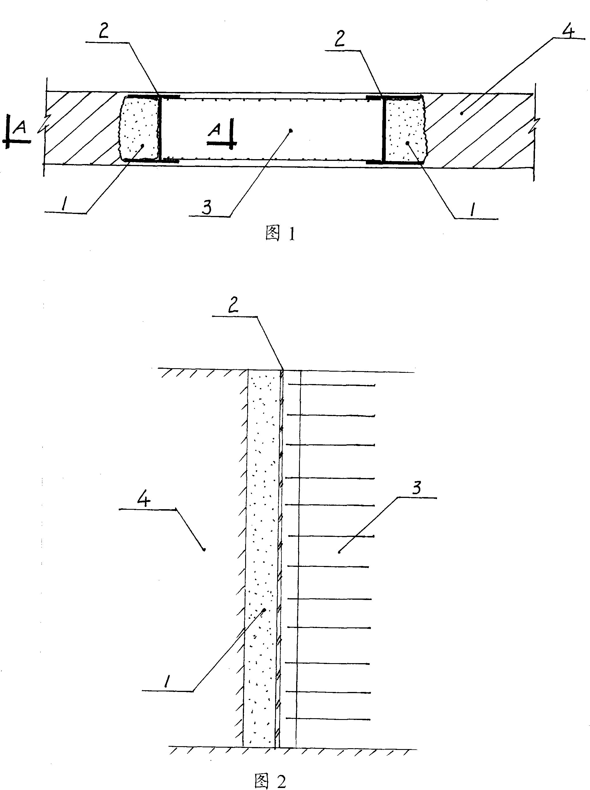
[0020] Embodiment 1: Referring to Fig. 1 and Fig. 2, this embodiment adopts an integral capsule body 1, and the filling in the capsule body 1 is gas, water or mud to form an air bag, water bag or mud bag for the I-shaped joint 2 The underground diaphragm wall is under construction. The capsule body 1 is installed between the joints 2 of the first-stage and second-stage grooves and the soil 4 of the second-stage groove. It can be installed into the groove section together with the diaphragm wall steel bars. It can be filled with fillers into the capsule body 1 first, and then the capsule body 1 can be put into the groove section; or the capsule body 1 can be put into the groove section first. , and then fill the capsule 1 with fluid fillings such as gas, water or mud, so that the capsule can be in contact with the inner wall of the joint 2 of the first-stage and second-stage grooves and the soil 4 of the second-stage groove, so as to prevent the concrete from flowing around to ...

Embodiment 2

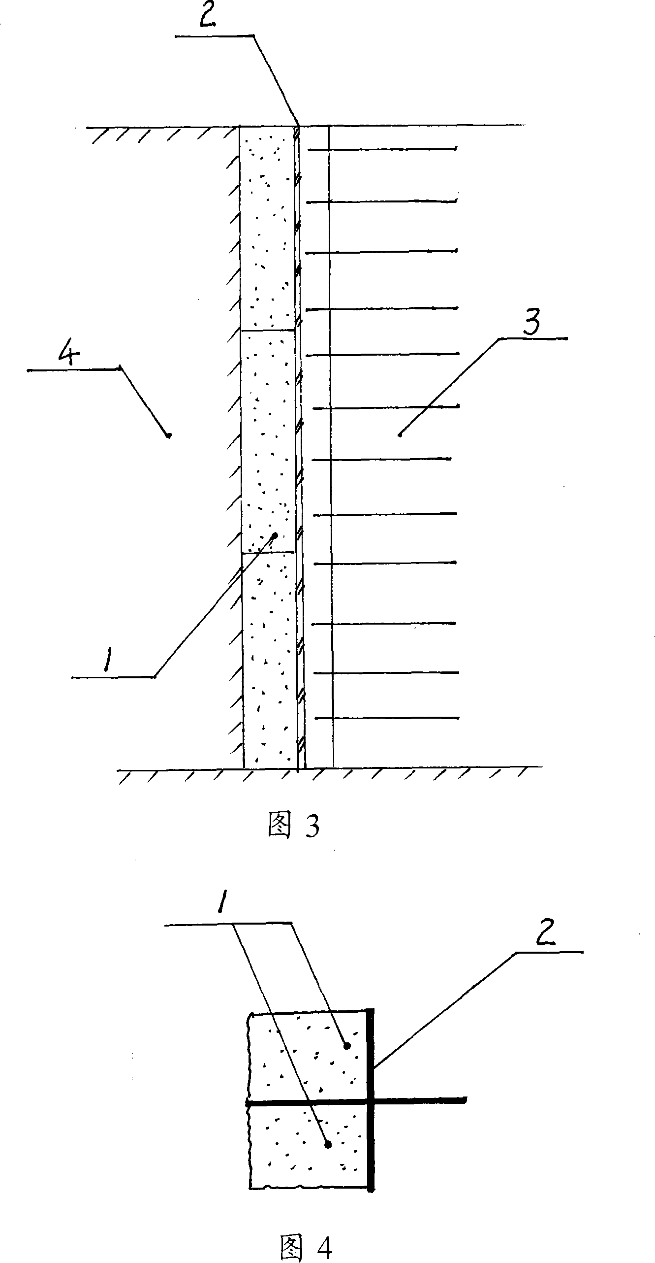
[0021] Embodiment 2: Referring to Fig. 1 and Fig. 3, this embodiment adopts a split-type capsule 1, which is composed of multiple capsules spliced ​​together, and the filling in the capsule 1 is soil, sand or stone chips, which is used for the I-shaped joint 2 The underground diaphragm wall is under construction. The capsule body 1 is installed between the joint 2 of the first-stage and second-stage grooves and the soil 4 of the second-stage groove. Install the capsule body in 2. When installing the capsule body, fill the capsule body 1 with solid fillings such as earth, sand or stone chips; then put multiple capsule bodies 1 into the joint 2 so that the capsule body can be connected , The inner wall of the joint 2 of the second-stage tank is in contact to prevent the concrete from flowing around to the second-stage tank section.

Embodiment 3

[0022] Embodiment 3: Referring to Fig. 4, the present embodiment adopts a split-type capsule 1, which is composed of two capsules, and the filling in the capsule 1 is gas, water or mud to form an air bag, water bag or mud bag for use in In the construction of the underground diaphragm wall of the cross-shaped joint 2, the capsule body 1 is installed between the joint 2 of the first-stage and second-stage troughs and the soil 4 of the second-stage trough, and the steel bars and joints of the first-stage trough section 3 are installed in the trough section The capsule body 1 has been installed in the joint 2 before, and installed in the groove section together with the continuous wall steel bars, the capsule body 1 can be filled with filling materials such as gas, water or mud first, or the capsule body 1 can be filled in the back Filling materials such as gas, water or mud. After being filled with fillers, the capsule body can be in contact with the inner wall of the joint 2 of...


PUM


Abstract

The invention relates to a flexible device of continuous concrete wall for preventing concrete flow around, which is characterized in that the flexible device comprises a capsule and filling in the capsule, wherein the capsule is located between the connector of the first-period groove and the second-period groove and the earth of the second-period groove, and the periphery of the capsule can contact with the inner walls of the connector of the first-period groove and the second-period groove after the capsule is filled with filling. The flexible device has the characteristics of excellent compactness, convenient construction and high efficiency, solves the problem that a rigid device can not be pulled out expressing in the background technology, and can effectively prevent the concrete flow around to the second-period groove section to affect the construction of the second-period groove section when used on the first-period groove section construction of the continuous concrete wall.

Description

technical field [0001] The invention relates to an underground diaphragm wall in the fields of civil engineering, construction, municipal engineering, water conservancy and the like, and in particular to a flexible device for preventing concrete from bypassing the underground diaphragm wall. Background technique [0002] When the existing underground diaphragm wall is constructed in the first-stage trough section, the phenomenon of concrete flowing around the second-stage trough section often occurs. The conventional treatment method is to use elastic steel sheets, colored strips or foam at the joints of the first-stage trough section And other ways to prevent concrete circumvention, but the effect is not ideal. The main problems are as follows: first, the concrete in the first-stage trough will flow around to the second-stage trough, wasting a lot of concrete; second, the steel bars in the second-stage trough cannot be installed in place; third, the construction of the seco...

Claims


Application Information

Patent Timeline
Patent Type & Authority Applications(China)
IPC IPC(8): E02D5/18E02D29/02
Inventor 王平
Owner 王萍
Why Eureka
Try Eureka