Laser angle interferometry system possessing standard angle rotating platform and its measurement method

A standard angle and angle technology, applied in the field of laser interferometry angle measurement system, can solve the problems of initial zero position error, limited application range, large measurement error, etc.

Inactive Publication Date: 2008-08-06
CHENGDU TOOL RES INST
View PDF0 Cites 32 Cited by
  • Summary
  • Abstract
  • Description
  • Claims
  • Application Information

AI Technical Summary

Problems solved by technology

[0009] 2. The error caused by the initial zero position: the laser angle interferometer requires that the laser beam be perpendicular to the conical point connecting the two angled prisms of the angle reflector at the beginning of the measurement, which is often difficult to achieve in actual operation
[0010] 3. Inaccurate angle reflector constant A will cause large measurement errors: Figure 4 shows the influence of different angle reflector constant A (corre

Method used


Image

  • Laser angle interferometry system possessing standard angle rotating platform and its measurement method
  • Laser angle interferometry system possessing standard angle rotating platform and its measurement method
  • Laser angle interferometry system possessing standard angle rotating platform and its measurement method

Examples


Embodiment 1

[0071] Embodiment 1: A laser angle interferometry system with a standard angle turntable measures any angle, the steps are as follows:

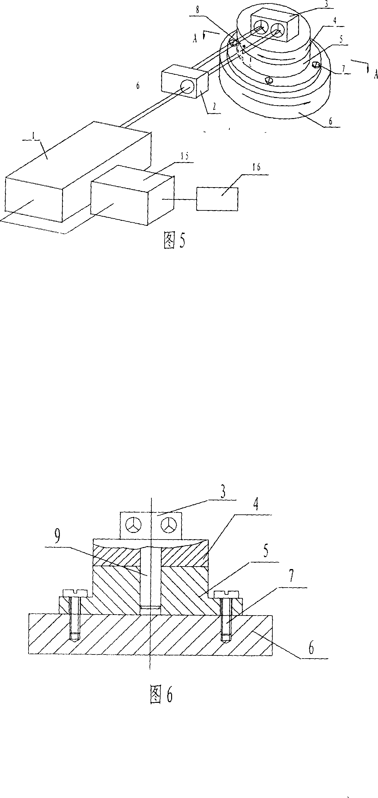
[0072] (1) Rotate the turntable upper plate 4 so that the angle mark 8 on the side circumference points to the mark line b between a and c on the turntable chassis 5 side circumference, adjust the turntable upper plate 4, the turntable chassis 5 and the angle reflector 3 as a whole , so that the surface of the angle reflector 3 is perpendicular to the incident laser beam, fasten the turntable chassis 5 and the measured turntable 6, and the computer clears the system and sets the angle reflector 3 at the zero position clockwise. Laser angle interferometer display It is "+"; (2) Calibration starts, rotate the upper disc 4 of the turntable until the angle mark 8 on its side circumference points to the position of the mark line a on the side circumference of the turntable chassis 5 and locks it, and the computer records the reading ρ of the laser ...

Embodiment 2

[0086] Embodiment 2: A laser angle interferometry system with a standard angle turntable detects the positional accuracy of the CNC turntable, the steps are as follows:

[0087] The installation of the system is the same as that in Figure 5. The tested turntable 6 is the tested CNC turntable. The detection interval of the CNC turntable is selected as r, and r is smaller than the total range of the laser angle interferometer. The specific operation steps are as follows:

[0088] Steps (1)-(3) are the same as in Embodiment 1, which is a calibration process. Measurement starts from step (4):

[0089] (4) Rotate the upper plate 4 of the turntable until the angle mark 8 on its side circumference points to the position of the mark line b on the side circumference of the turntable chassis 5 and locks it. The computer clears the system and sets the angle mirror 3 clockwise at the zero position. The direction of the laser angle interferometer is displayed as "+"; (5) Rotate the upper ...


PUM


Abstract

The invention relates to a laser angle interferometry system provided with a turntable with standard angle and a measuring method, which resolves problems that measuring range of the existing laser angle interferometer is small, initial zero error and error of reflector constant A influences the measurement accuracy. A laser head (1) is fixed at an angle interferometer (2), a top wall (4) of the turntable with standard angle is connected with an angle reflector (3), wherein laser emitted from the laser head (1) projects to the angle reflector (3), the top wall (4) of the turntable is in tight fit with a spindle (9), a chassis of the turntable (5) is in movable fit with the spindle (9), the top wall (4) of the turntable and the chassis of the turntable can be rotated relatively, further the chassis of the turntable is connected with a turntable to be measured (6) via a bolt (7). When measuring, the top wall (4) of the turntable and the angle reflector (3) can rotate in identical angle in opposite directions in sequence with respect to integer of the turntable to be measured (6), the chassis of the turntable (5), the top wall of the turntable (4) and the angle reflector (3), ensuring laser beam is not deviated from the angle reflector (3), reading each readout of the laser angle interferometer after rotating in sequence, and obtaining measured value of each arbitrary angle by calculating.

Description

Technical field: [0001] The invention relates to a system and a method for measuring angles by laser interferometry. Background technique: [0002] Laser angle interferometer is mainly used for angle measurement, including precision angle detection of rotary table, CNC machine tool turntable and other devices. [0003] The principle of traditional laser angle interferometer is shown in Figure 1. [0004] The laser light emitted by the laser head 1 is divided into two paths in the angle interferometer 2, pointing to the two angle prisms in the angle reflector 3 respectively. When the angle reflector rotates from the original position E to the F position, the corresponding rotation angle is α, The optical path of the laser passing through the two angular prisms changes δ, and the rotation angle of the angular reflector is obtained by the following formula: [0005] α=arcsin(δ / A) [0006] A is the angular reflector constant, which is the distance between the ...

Claims


Application Information

Patent Timeline
IPC IPC(8): G01B11/26
Inventor 舒阳邱易李立群蒋金志羡一民
Owner CHENGDU TOOL RES INST
Why Eureka
Try Eureka