Ultrasonics wind velocity indicator and method for measuring wind velocity and wind direction by ultrasonic

An ultrasonic and anemometer technology, used in fluid velocity measurement, velocity/acceleration/impact measurement, measurement devices, etc., can solve the problems of low measurement accuracy, short service life, and large environmental impact, saving maintenance costs and improving measurement. The effect of precision and simple equipment structure

Inactive Publication Date: 2008-08-06
钟永勇
View PDF0 Cites 49 Cited by
  • Summary
  • Abstract
  • Description
  • Claims
  • Application Information

AI Technical Summary

Problems solved by technology

The device measures the time difference between the forward and reverse directions of the ultrasonic waves transmitted along the air to the receiving end through two relatively fixed pairs of ultrasonic transmitting/receiving probes, and uses the time difference method to calculate the air f

Method used


Image

  • Ultrasonics wind velocity indicator and method for measuring wind velocity and wind direction by ultrasonic
  • Ultrasonics wind velocity indicator and method for measuring wind velocity and wind direction by ultrasonic
  • Ultrasonics wind velocity indicator and method for measuring wind velocity and wind direction by ultrasonic

Examples


Embodiment 1

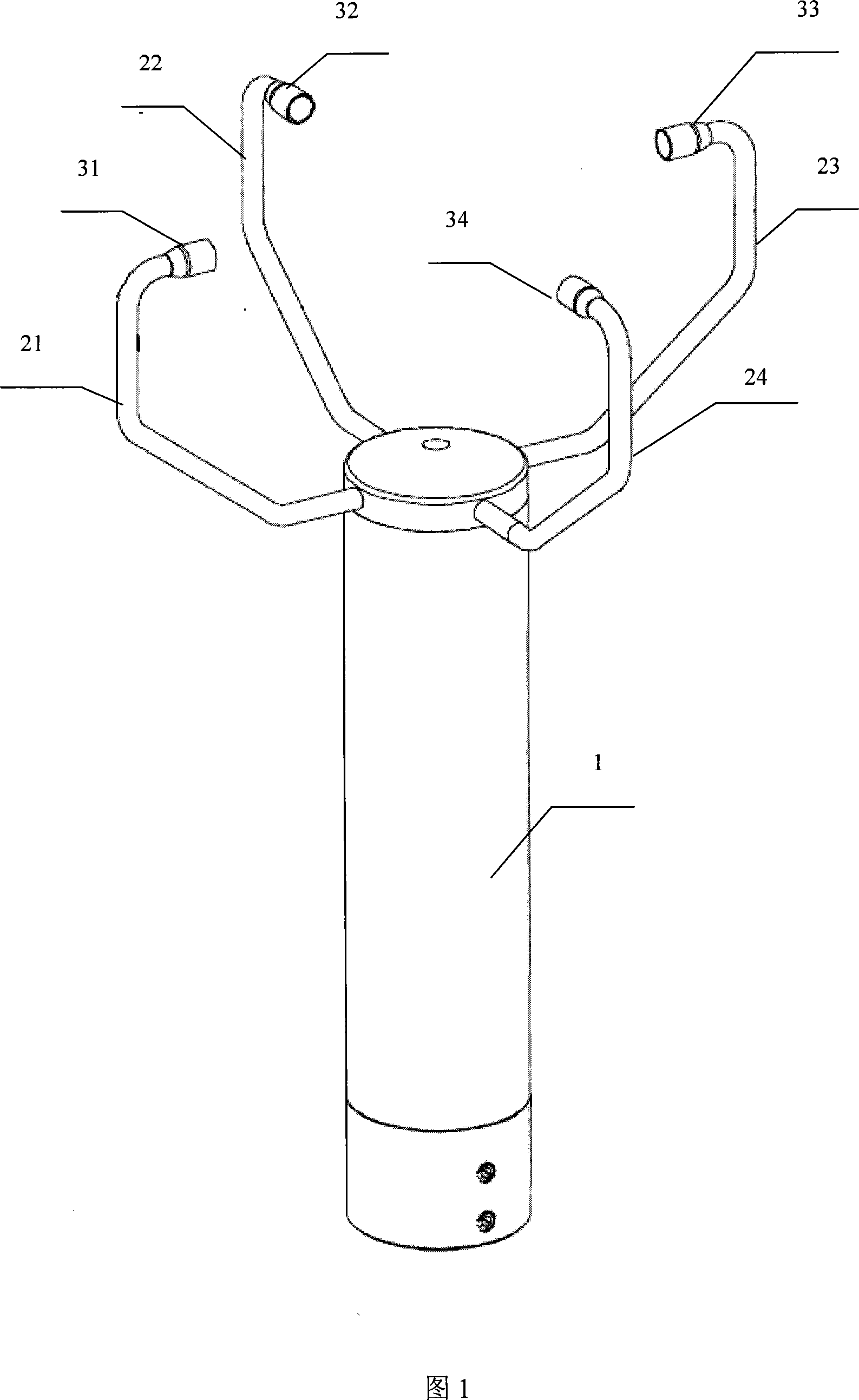
[0031] Referring to Fig. 1, the ultrasonic anemometer provided by the embodiment of the present invention includes a base 1, a control circuit board and four measuring arms mounted on the base: a first measuring arm 21, a second measuring arm 22, a third measuring arm 23 and a Four measuring arms 24 . The base 1 is a cylinder, and the four measuring arms are respectively installed on the same horizontal plane at the top of the base 1, and the adjacent measuring arms form an included angle of 90 degrees in turn. The measuring arm is formed by bending a hollow stainless steel tube, and an ultrasonic transmitting / receiving probe composed of an ultrasonic sensor is installed on the top of each measuring arm, respectively: the first ultrasonic transmitting / receiving probe 31, the second ultrasonic transmitting / receiving probe The receiving probe 32 , the third ultrasonic transmitting / receiving probe 33 and the fourth ultrasonic transmitting / receiving probe 34 . The first ultrasoni...

Embodiment 2

[0050] Figure 11 shows the schematic diagram of the method of using ultrasonic anemometer to measure wind speed and wind direction with ultrasonic waves. This method uses the time difference method to measure the time difference between the forward and reverse directions of the ultrasonic wave propagating along the air and arrive at the receiving end to calculate the air flow velocity. .

[0051] Through the ultrasonic anemometer provided in Example 1, the ultrasonic transmitting / receiving probe is used as the ultrasonic transmitting / receiving device to describe in detail the method for measuring wind speed and wind direction provided by the embodiment of the present invention, which specifically includes the following steps, see Figure 1 and Figure 12:

[0052] Step 200: the first ultrasonic transmitting / receiving probe 31 sends ultrasonic waves to the third ultrasonic transmitting / receiving probe 33, and measures the propagation time of ultrasonic waves between the first ult...


PUM


Abstract

The invention discloses an ultrasonic anemoscope, which comprises a base plate, a control circuit board, four measuring arms and four ultrasonic wave transmitting/receiving probes. The four measuring arms are respectively connected with the base plate and are adjacent in turn to form 90 DEG included angles; the four ultrasonic wave transmitting/receiving probes are respectively arranged on one ends of the four measuring arms away from the base plate, and the two pairs of probes which form 180 DEG angles oppositely are arranged in the same plane and have equal vertical distances from the base plate. The invention also discloses a method of measuring wind velocity and direction through ultrasonic wave, which comprises the following steps of measuring the time difference of the ultrasonic wave which is transmitted towards the positive and negative directions, travels in the air and reaches the receiving ends through the opposite two pairs of ultrasonic wave transmitting/receiving probes; calculating the air flow velocity through integrally considering the distances between the probes. The ultrasonic anemoscope solves the technical problem that an action part obtains measurement information, improves the measurement accuracy and prolongs the service of the apparatus, thereby being applicable to various bad measurement surroundings.

Description

technical field [0001] The invention relates to the technical field of wind speed and wind direction measurement, in particular to an ultrasonic anemometer and a method for measuring wind speed and wind direction by using ultrasonic waves. Background technique [0002] At present, the existing anemometers mainly include mechanical anemometers and thermal anemometers. Among them, the mechanical anemometer mainly obtains basic measurement information through the rotation of the impeller driven by the wind force, and converts the angular velocity of the impeller rotation or the number of revolutions of the impeller into an electrical signal, and calculates the wind speed based on this. However, this kind of anemometer has relatively high requirements for the measurement environment, and because the sealing problem of the instrument is not solved, it cannot work normally in the sandstorm weather in the north, and the moving parts will be stuck due to freezing in the low temperat...

Claims


Application Information

Patent Timeline
IPC IPC(8): G01P5/18G01P13/02G01P5/24
Inventor 钟永勇
Owner 钟永勇
Why Eureka
Try Eureka