
Carbon dioxide heat pump control method based on pressure-temperature

A carbon dioxide and control method technology, applied in heat pumps, refrigerators, refrigeration components, etc., can solve the problems of complex, no carbon dioxide heat pump systems, work performance coefficients, specific control methods, large throttling losses, etc., and achieve a good COP value. Effect

Active Publication Date: 2008-08-13
RES INST OF XIAN JIAOTONG UNIV & SUZHOU
View PDF0 Cites 27 Cited by
  • Summary
  • Abstract
  • Description
  • Claims
  • Application Information

AI Technical Summary

Problems solved by technology

However, it also has many problems: the critical temperature is 31°C, and the high-pressure side of the system cycle is in a near-critical or supercritical state under normal temperature cooling conditions; the system pressure is very high; the throttling loss is very large
[0004] Due to the high pressure on the high-pressure side of the system, which can reach more than 100bar, and the change of carbon dioxide on the high-pressure side is in a supercritical state, it is more complicated. These make the carbon dioxide heat pump different from conventional heat pumps, and the control is relatively difficult
At present, research on carbon dioxide heat pumps is being carried out both at home and abroad, and some studies on control methods have been seen, but most of them are aimed at the overall operation process of the system, and no specific control is proposed for improving the performance coefficient of carbon dioxide heat pump systems. method

Method used


Image

  • Carbon dioxide heat pump control method based on pressure-temperature
  • Carbon dioxide heat pump control method based on pressure-temperature
  • Carbon dioxide heat pump control method based on pressure-temperature

Examples


Embodiment Construction

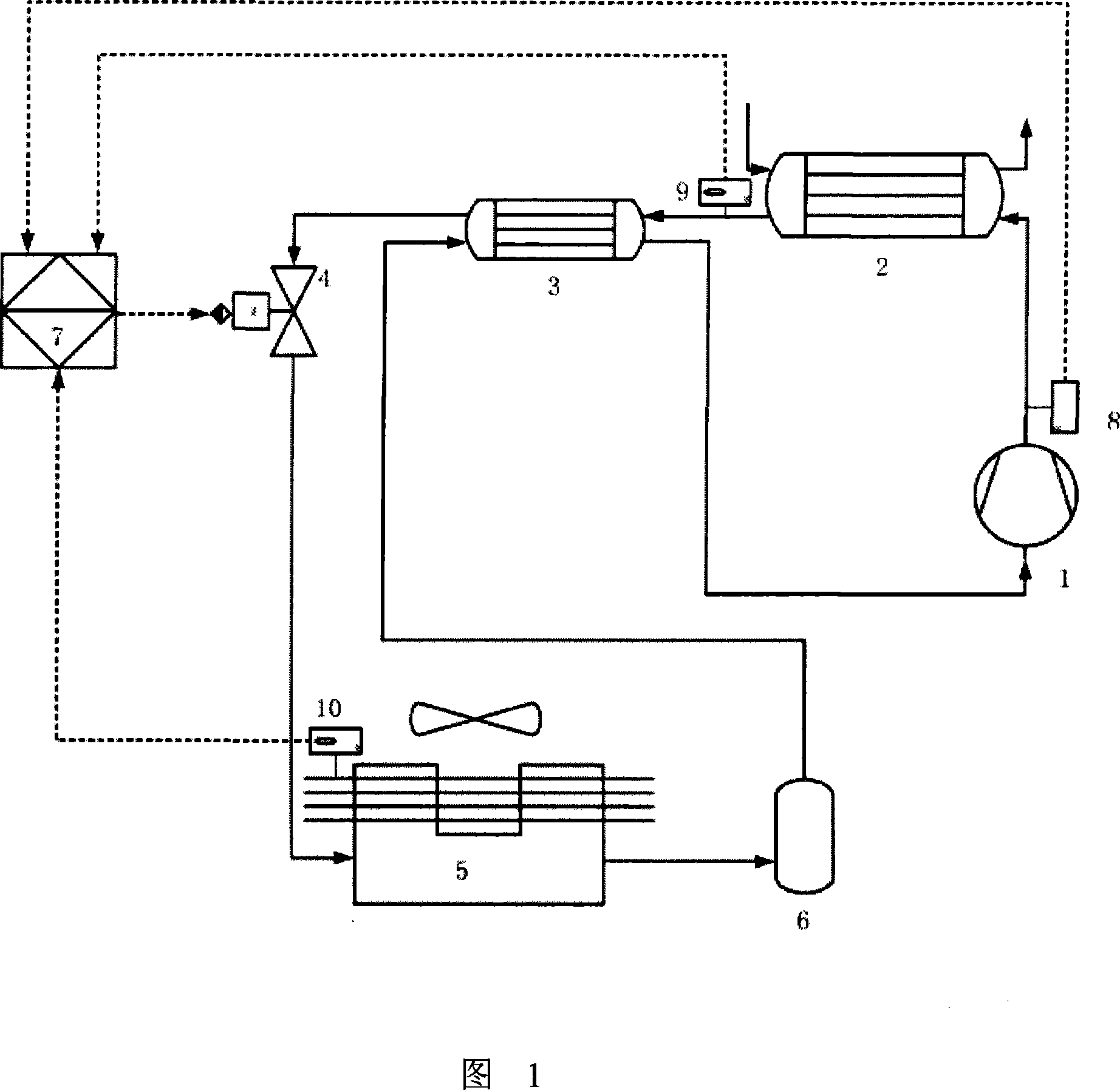
[0016] Referring to Fig. 1, the flow chart of the carbon dioxide heat pump system of the present invention is as follows: after the carbon dioxide gas enters the compressor 1 and is compressed, the high-temperature and high-pressure carbon dioxide gas enters the gas cooler 2 for cooling, and the released heat is used for heating hot water, and the supercritical carbon dioxide gas after cooling The gas enters the intermediate heat exchanger 3 for further cooling, and then passes through the throttling of the electronic expansion valve 4, enters the evaporator 5 for evaporation and heat exchange, and the low-temperature and low-pressure carbon dioxide refrigerant passes through the gas-liquid separator 6 to separate the low-temperature and low-pressure carbon dioxide refrigerant The agent gas enters the intermediate heat exchanger 3, further cools the supercritical carbon dioxide gas coming out of the gas cooler, and returns to the compressor 1 to complete a cycle. Due to control...


PUM


Abstract

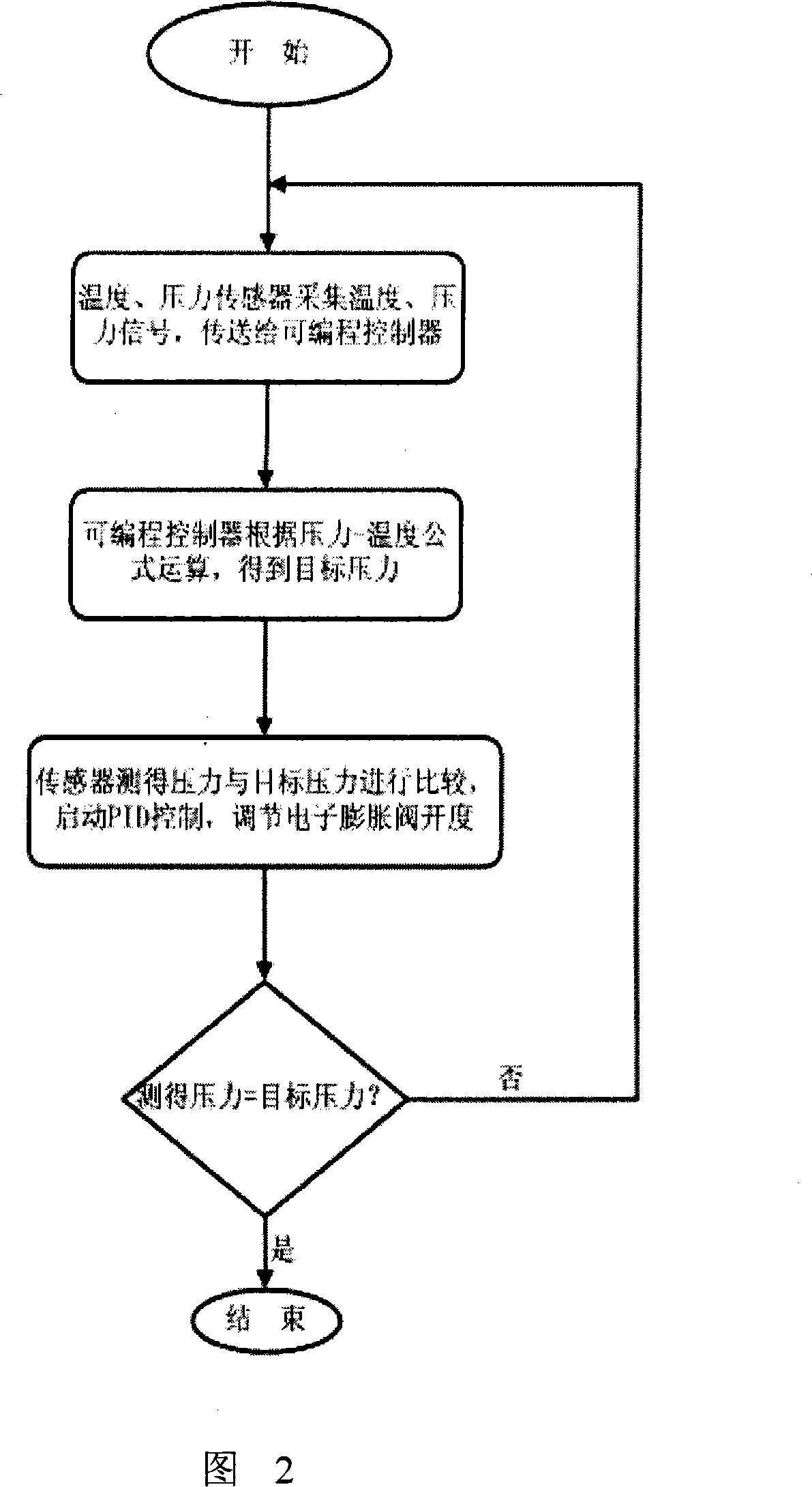
A control method based on pressure-temperature carbon dioxide heat pump firstly collects the refrigerant temperature of air cooler outlet of the heat pump system, evaporator wing temperature and refrigerant pressure at the outlet of the compressor; then the method transmits the collected temperature signal to the control device to obtain the target pressure of refrigerator at the outlet of the compressor; and then the method compares the refrigerant pressure at the outlet of the compressor collected by the pressure sensor to the target pressure of refrigerator at the outlet of the compressor, obtaining a control signal for controlling the opening of the electrical expansion valve, so that the method controls the operating parameter of the entire system; this method also circulatorily collects temperature, pressure signals and finally achieves that the refrigerant pressure at the compressors reaches target pressure. This invention achieves the control of the electrical expansion valve via collecting the refrigerant temperature of air cooler outlet of the heat pump system, evaporator wing temperature and refrigerant pressure at the outlet of the compressor to adjust pressure of the heat pump system, reaching great COP value.

Description

technical field [0001] The invention relates to a control method of a carbon dioxide heat pump, in particular to a control method of a pressure-temperature-based carbon dioxide heat pump. Background technique [0002] In recent years, the natural working substance carbon dioxide has been paid more and more attention by the refrigeration industry because of its non-toxic, non-flammable, ozone destruction index ODP of 0, and global warming potential GWP of 1. The application research of carbon dioxide as a refrigerant It is also becoming more and more important. However, it also has many problems: the critical temperature is 31°C, and the high-pressure side of the system cycle is in a near-critical or supercritical state under normal temperature cooling conditions; the system pressure is very high; the throttling loss is very large. All of these make it difficult to control the system in which carbon dioxide is used as the refrigerant. [0003] The main components of the exi...

Claims


Application Information

Patent Timeline
IPC IPC(8): F25B49/02F25B30/02
Inventor 曹锋柴抗抗王守国邢子文
Owner RES INST OF XIAN JIAOTONG UNIV & SUZHOU
Learn More