Large-sized optical flat interferometry device and method

An optical plane, interferometric measurement technology, applied in the field of optical testing, can solve the problems of increasing production cost, affecting measurement accuracy, low lateral resolution, etc., achieving the effect of simple structure, reducing cost, and improving lateral resolution

Inactive Publication Date: 2008-08-13
NAT UNIV OF DEFENSE TECH
View PDF5 Cites 23 Cited by
  • Summary
  • Abstract
  • Description
  • Claims
  • Application Information

AI Technical Summary

Problems solved by technology

Another option is to use the Ritchey-Common measurement method, refer to the Zygo company's wave surface interferometer product manual, it needs to add a large optical spherical mirror, and may introduce off-axis aberrations to affect the measurement accuracy
The above two methods are commonly used at present, but they will greatly increase the production cost, and it is not easy to popularize and use them in production practice.
At the same time, the lateral resolution of the above two methods is relatively low, which cannot meet the requirements of high-resolution measurement

Method used


Image

  • Large-sized optical flat interferometry device and method
  • Large-sized optical flat interferometry device and method
  • Large-sized optical flat interferometry device and method

Examples


Embodiment Construction

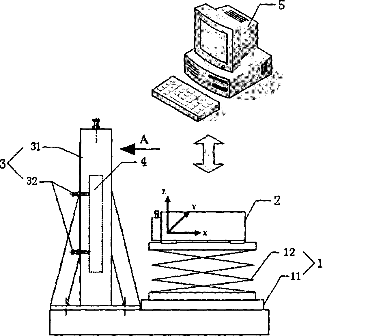
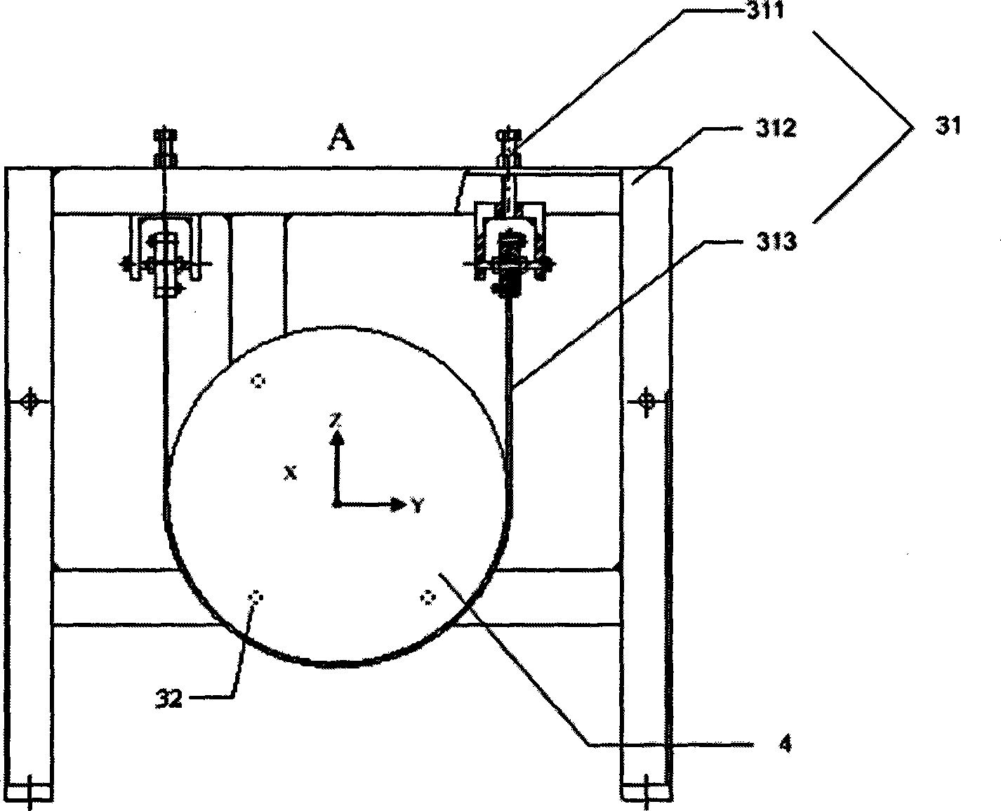
[0031] Such as figure 1 As shown, the large-scale optical plane interferometric measurement device of the present invention has an interferometer two-axis linear motion adjustment platform 1, and is located in front of the adjustment platform 1 and is provided with a two-dimensional tilt adjustment platform 3 for the plane mirror to be measured. The adjustment platform 1 is equipped with a laser wavefront interference The instrument 2 is connected with the laser wave surface interferometer 2 and has a main control computer 5 with a built-in measurement data processing algorithm program, and the measured plane mirror 4 is installed on the adjustment platform 3 during measurement.

[0032] The interferometer two-axis linear motion adjustment platform 1 includes a horizontal Y-axis motion assembly 11 and a vertical Z-axis motion assembly 12 superimposed on the Y-axis assembly. The Y-axis assembly 11 is composed of an AC servo motor and its encoder, and an elastic coupling. The Z-...


PUM


Abstract

The invention discloses a device and method of interferometry for a large-scale optical plane. Wherein, the interferometry device comprises an adjustment platform for the two-axis linear motion of an interferometer, a two-dimensional tilt adjustment platform for the measured plane mirror located at the front of the adjustment platform, a laser wave-front interferometer installed in the adjustment platform for the two-axis linear motion of an interferometer and a control computer contained the program of measured data processing algorithm, which is connected to the laser wave-front interferometer. With the device, a plurality of obtained error surface maps of partial region can be spliced to an error surface map containing medium-high frequency (MHF) band on the whole caliber according to the measured data processing algorithm through the control computer, which includes a method for determining the initial position, an algorithm for extracting data from the overlap region and an algorithm for splicing the area data. The invention is a device and method of interferometry for a large-scale optical plane with low cost, high precision and high efficiency.

Description

technical field [0001] The invention belongs to the technical field of optical testing, and mainly relates to an interference measurement device and method for a large optical plane. Background technique [0002] With the continuous development of optical processing and detection technology, large-aperture optical systems have been more and more widely used in the fields of astronomy, space optics, and military affairs. bigger. On the other hand, the aberration-free point method interferometry of the large-aperture parabolic primary mirror commonly used in astronomical telescopes also requires high-precision large optical flat mirrors. [0003] In the polishing process of large optical planes, the surface error is mainly measured by laser wavefront interferometer. However, the measurable effective aperture of the commonly used laser wavefront interferometer cannot be larger than the aperture of its reference lens, which makes the interferometric measurement of large optica...

Claims


Application Information

Patent Timeline
Patent Type & Authority Applications(China)
IPC IPC(8): G01B11/24G01B9/02G01M11/00G01M11/02
Inventor 李圣怡戴一帆陈善勇丁凌艳郑子文刘晓东尹自强
Owner NAT UNIV OF DEFENSE TECH
Why Eureka
Try Eureka