
Polarization antenna for directional coupler feedback low profile back cavity round

A technology of directional coupler and circularly polarized antenna, which is applied in the direction of antenna, slot antenna, circuit, etc., can solve the problems of large size and incapable of planar integration, low gain axial ratio, low axial ratio bandwidth, and incapable of planar integration, etc., to achieve excellent radiation characteristics , Improve the actual use bandwidth, improve the effect of 3dB axial ratio bandwidth

Inactive Publication Date: 2012-06-20
浙江博凯仪表有限公司
View PDF3 Cites 0 Cited by
  • Summary
  • Abstract
  • Description
  • Claims
  • Application Information

AI Technical Summary

Problems solved by technology

Compared with the previous cavity-backed circularly polarized antenna, this implementation method is greatly reduced in size, but its processing cost is still high, and it cannot be integrated in a plane; the helical antenna is mainly used in space applications of earth stations and satellite links. It has the advantages of high gain, low axial ratio, and wide axial ratio bandwidth, but its three-dimensional helical radiation structure determines its disadvantages such as large volume and incapable of plane integration.

Method used


Image

  • Polarization antenna for directional coupler feedback low profile back cavity round
  • Polarization antenna for directional coupler feedback low profile back cavity round
  • Polarization antenna for directional coupler feedback low profile back cavity round

Examples


Embodiment Construction

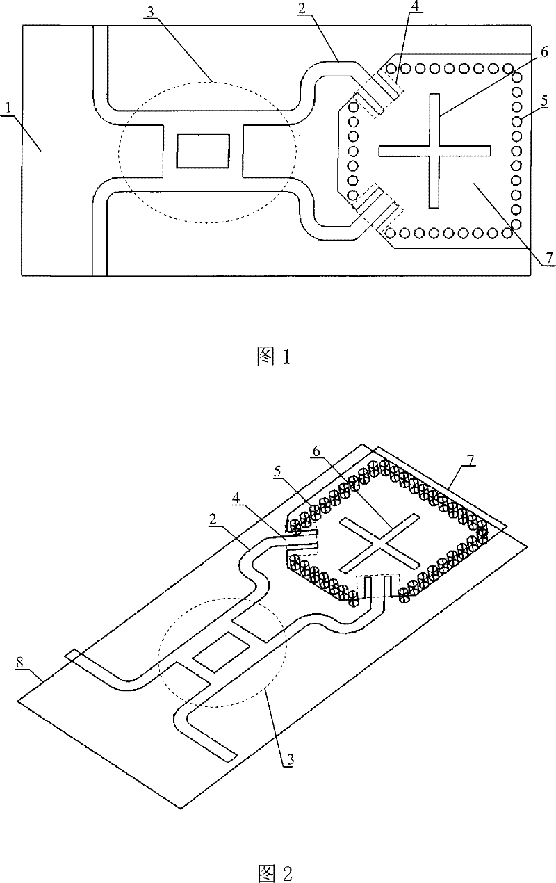
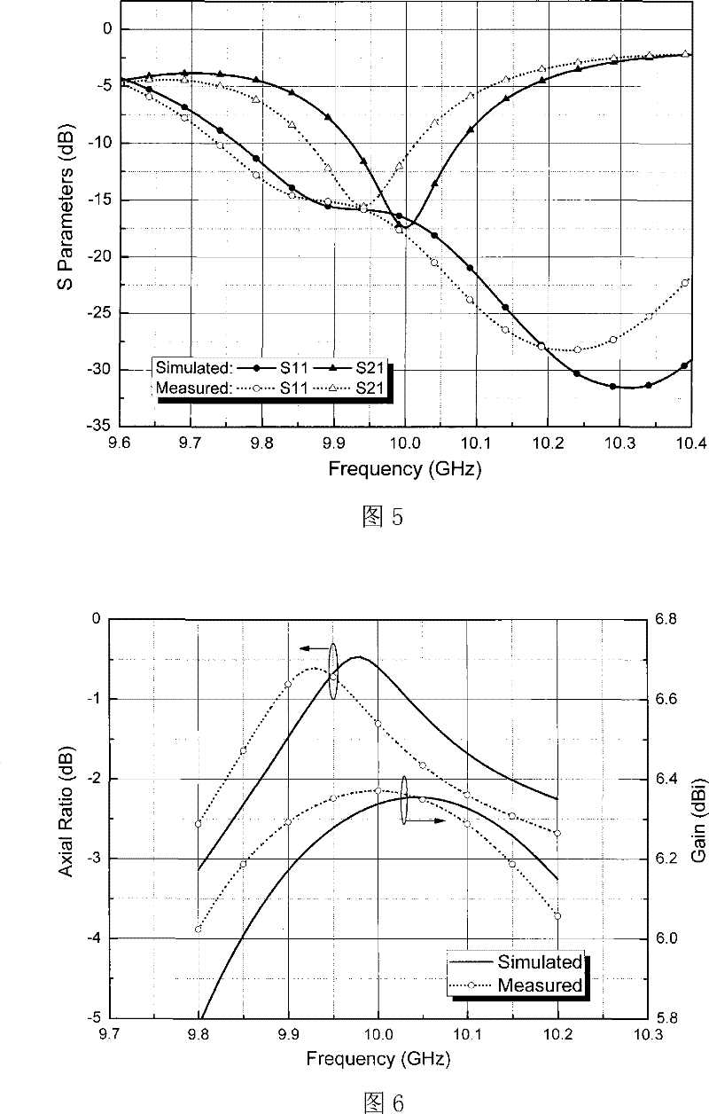
[0024] like figure 1 and 2 As shown, the directional coupler fed low-profile cavity-backed circularly polarized antenna includes a Rogers5880 dielectric substrate 1 with a thickness of 0.5 mm, and the two sides of the dielectric substrate 1 are coated with metal layers, which are respectively an upper metal layer 7 and a lower metal layer 8, Wherein the lower metal layer 8 is used as the stratum. like image 3, the upper metal layer 7 is etched with a microstrip line 2 for feeding, a branch line directional coupler 3 in the form of a microstrip (the dotted line oval frame contains the part) and a coplanar waveguide transmission line 4 (the dotted line box contains the part), and the coplanar waveguide The transmission line 4 is a common-ground coplanar waveguide structure, the metal strip in the middle of which extends outward, and is connected to the two output ends of the branch line directional coupler 3 as a microstrip line 2 . The width of the 50 ohm microstrip line is...


PUM


Abstract

The present invention relates to a directional coupler feed low-profile cavity-backed circularly polarized antenna. The common cavity-backed circularly polarized antenna has complicated structure and large volume and can be planely integrated. In the invention two surfaces of the medium substrate is plated with metal layers, the upper metal layer is etched for the feed microstrip line, the branchline directional coupler with a microstrip form and the co-ground coplanar waveguide transmission line, a plurality of plated-through holes which are arranged to a square are arranged penetrating theupper metal layer, the medium substrate and the lower metal layer, the cavity is formed and the coplanar waveguide transmission line extends into the cavity. The lower metal layer is etched with two elongated radiating gap which are perpendicular to each other. Comparing with the existing cavity-backed circularly polarized antenna the invention adopts the 3dB directional coupler with 90 degree phase shift as the feed network, on the base of reserving the high grin character of the cavity-backed circularly polarized antenna, and the 3dB axial ratio bandwidth of the antenna is evidently increased. The whole structure can be manufactured with the PCB technique and the cost is low, the structure can be integrated with plane circuit seamlessly and the integrity is increased.

Description

technical field [0001] The invention belongs to the field of microwave technology, and relates to a directional coupler-feeding low-profile cavity-backed circularly polarized antenna based on substrate integrated waveguide technology, which can be used as a radio frequency transceiver front-end antenna and is widely used in mobile communications, satellite communications, and radars. And other wireless communication systems, used to solve the polarization mismatch problem caused by Faraday electromagnetic rotation effect, etc., and can also play the role of suppressing rain and fog interference and anti-multipath reflection. Background technique [0002] As a key component of a communication system, antennas are widely used in wireless communication occasions. Due to the Faraday rotation effect of radio wave propagation in space and the uncertainty of the position of the receiving antenna in mobile communication, if a traditional single-polarized antenna is used as the trans...

Claims


Application Information

Patent Timeline
Patent Type & Authority Patents(China)
IPC IPC(8): H01Q1/38H01Q13/08H01Q13/10
Inventor 罗国清孙玲玲
Owner 浙江博凯仪表有限公司
Learn More