
Broadband circularly polarized microstrip antenna array

A technology of circularly polarized antennas and microstrip antennas, applied to antenna arrays, individually powered antenna arrays, antennas, etc., can solve the problems of increased difficulty in mass production, difficulty in forming antenna arrays, and narrow bandwidth of single-point feeds. Compact structure, improved 3dB axial ratio bandwidth, and improved antenna gain

Active Publication Date: 2020-06-02
DALIAN MARITIME UNIVERSITY
View PDF5 Cites 4 Cited by
  • Summary
  • Abstract
  • Description
  • Claims
  • Application Information

AI Technical Summary

Problems solved by technology

However, most single-point feeds have a narrow bandwidth, and a stacked structure is used to increase the bandwidth. However, the use of a stacked structure leads to complex processing technology, greatly increased difficulty in mass production, and it is difficult to form an antenna array.
The dual-point feed shaft has a wider bandwidth, but the longer the feeder, the greater the loss

Method used


Image

  • Broadband circularly polarized microstrip antenna array
  • Broadband circularly polarized microstrip antenna array
  • Broadband circularly polarized microstrip antenna array

Examples


Embodiment Construction

[0025] In order to make the technical solutions and advantages of the present invention more clear, the technical solutions in the embodiments of the present invention are clearly and completely described below in conjunction with the drawings in the embodiments of the present invention:

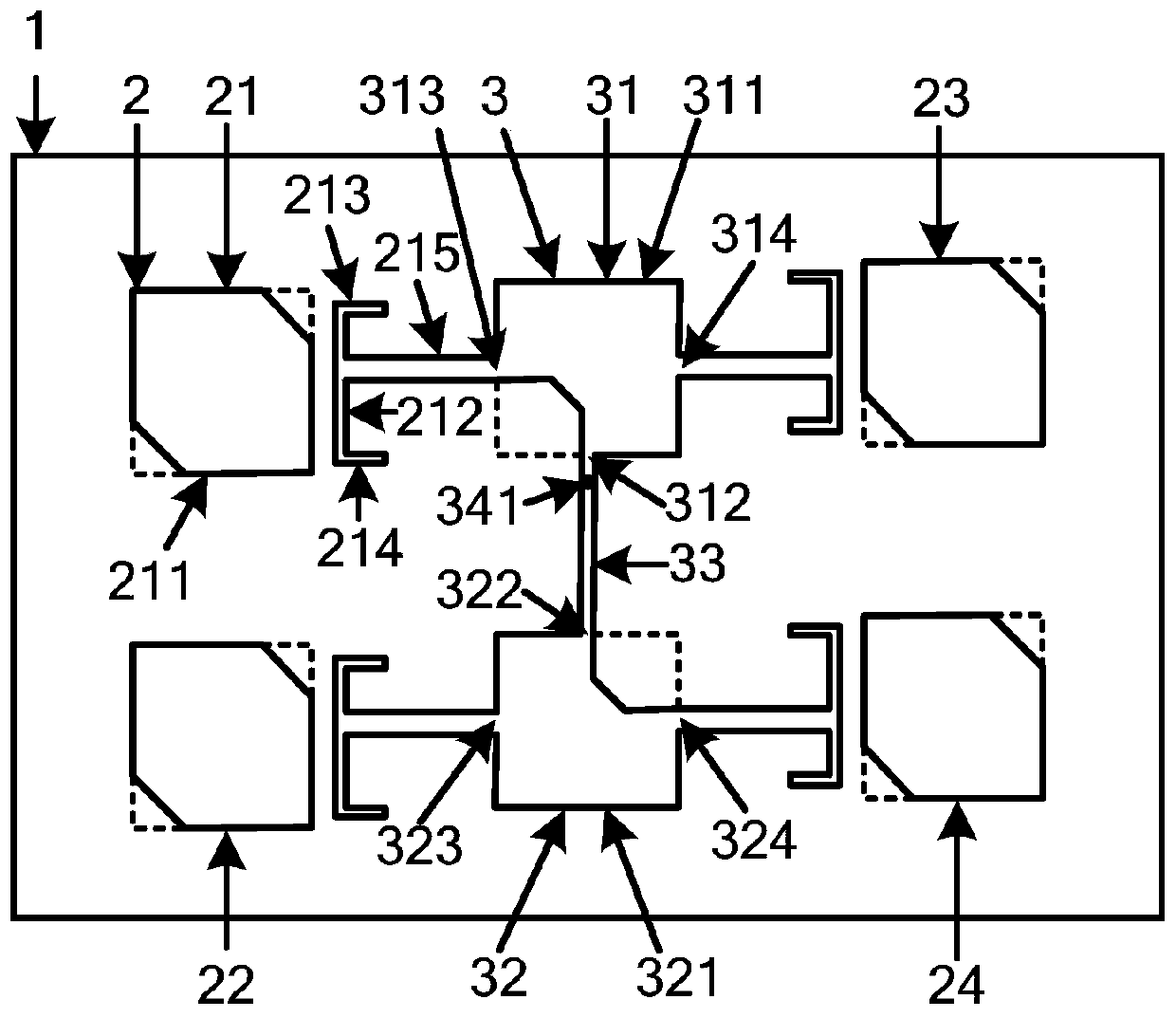
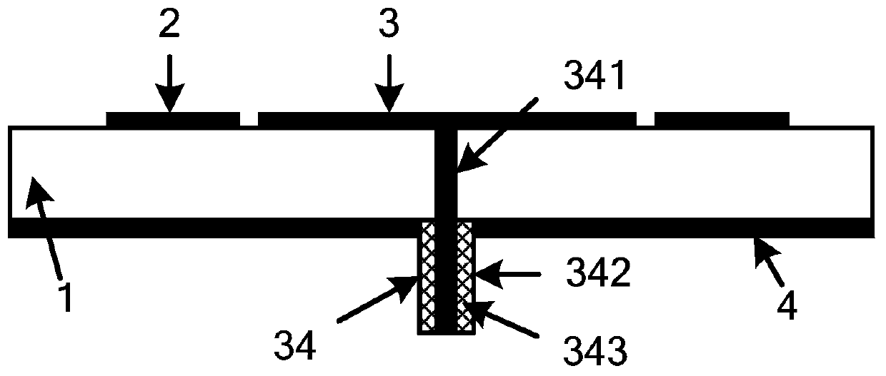
[0026] Such as figure 1 A broadband circularly polarized microstrip antenna array is shown, figure 1 It is a top view of the broadband circularly polarized microstrip antenna array of the present invention. figure 2 It is a side view of the broadband circularly polarized microstrip antenna array of the present invention. Such as figure 1 with 2 As shown, the antenna array includes a dielectric substrate 1 , a circularly polarized antenna 2 , a feeding network 3 and a metal floor 4 .

[0027] The circularly polarized antenna 2 is printed on the upper surface of the dielectric substrate 1 , and the metal floor 4 is printed on the lower surface of the dielectric substrate 1 .

[0028] The...


PUM


Abstract

The invention discloses a broadband circularly polarized microstrip antenna array, which specifically and structurally comprises a dielectric substrate, a circularly polarized antenna, a feed networkand a metal floor; the circularly polarized antenna is fixedly connected to the upper surface of the dielectric substrate, and the metal floor is fixedly connected to the lower surface of the dielectric substrate; the circularly polarized antenna comprises four side coupling circularly polarized antenna units with the same structure; each side coupling circularly polarized antenna unit comprises asquare corner cut radiation patch, a microstrip coupling line, a microstrip branch line I, a microstrip branch line II and a microstrip connecting line I; due to the adoption of the antenna units with the coupled side edges, the matching bandwidth of the antenna is increased; the 3dB axial ratio bandwidth of the circularly polarized antenna is broadened by adjusting the vertical branch lines loaded at the two sides of the side coupling line; besides, the feed network with the circularly polarized wave radiation function is adopted, so that the antenna size is reduced, the antenna gain is improved, and meanwhile, the antenna has the characteristics of compact structure, low manufacturing cost and the like.

Description

technical field [0001] The invention relates to the technical field of antennas, in particular to a broadband circularly polarized microstrip antenna array. Background technique [0002] Circularly polarized antennas can suppress the interference of external waves, reduce multipath propagation effects, and eliminate polarization distortion, so they are widely used in wireless communication systems such as radar, satellite, WIFI, RFID, and Bluetooth. With the rapid development of wireless communication technology, circularly polarized antennas are developing in the direction of broadband, low cost, and miniaturization. [0003] Microstrip antennas are widely used in the field of wireless communication due to their advantages of easy processing and light weight. There are many technical measures for microstrip antennas to achieve circular polarization, which can be roughly divided into single-point feeding and dual-point feeding, such as cutting angle perturbation, slotting o...

Claims


Application Information

Patent Timeline
Patent Type & Authority Applications(China)
IPC IPC(8): H01Q1/38H01Q1/50H01Q21/00H01Q21/06
CPCH01Q1/38H01Q1/50H01Q21/0006H01Q21/065
Inventor 王钟葆周建豪祝子辉房少军刘宏梅周芸
Owner DALIAN MARITIME UNIVERSITY
Learn More