Switch power control method and its device

A switching power supply and control method technology, applied in the direction of output power conversion devices, control/regulation systems, electrical components, etc., can solve the problems of large output voltage fluctuations, over-regulation or adjustment, and transient response speeds that need to be further improved , to achieve the effect of strong anti-interference ability and short response time

Inactive Publication Date: 2008-08-13
SOUTHWEST JIAOTONG UNIV
View PDF0 Cites 23 Cited by
  • Summary
  • Abstract
  • Description
  • Claims
  • Application Information

AI Technical Summary

Problems solved by technology

Its disadvantage is that in each switching cycle, as long as the output voltage is lower than the reference voltage, regardless of the difference, there is a current reference value I 1 To determine the duty cycle of high-energy pulses, more serious overshoot or under-regulation often occurs; when low-energy control pulses are adjusted,

Method used


Image

  • Switch power control method and its device
  • Switch power control method and its device
  • Switch power control method and its device

Examples


Embodiment 1

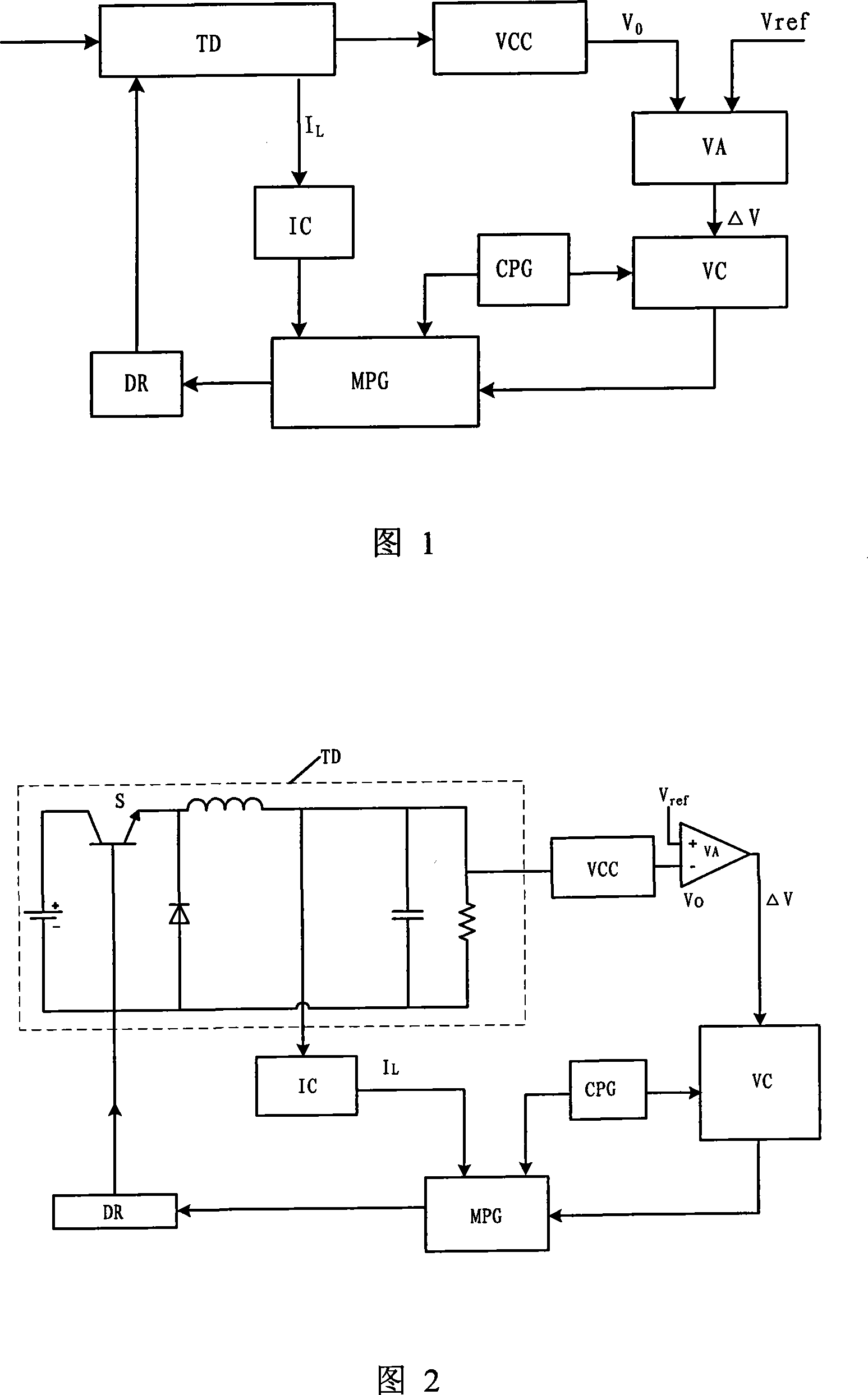
[0050] Fig. 1 shows, a kind of embodiment of the present invention is, a kind of control method of switching power supply, and its specific method is:

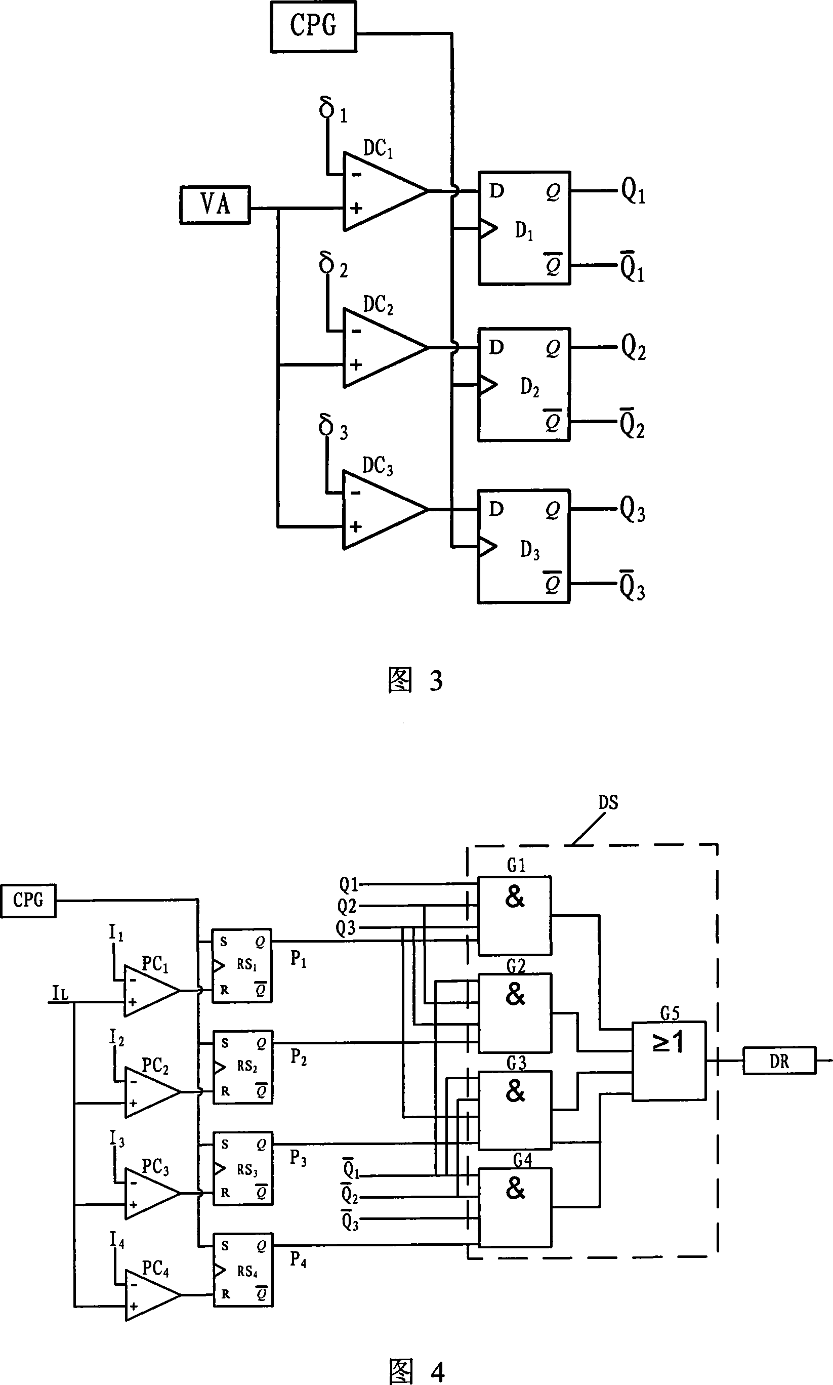
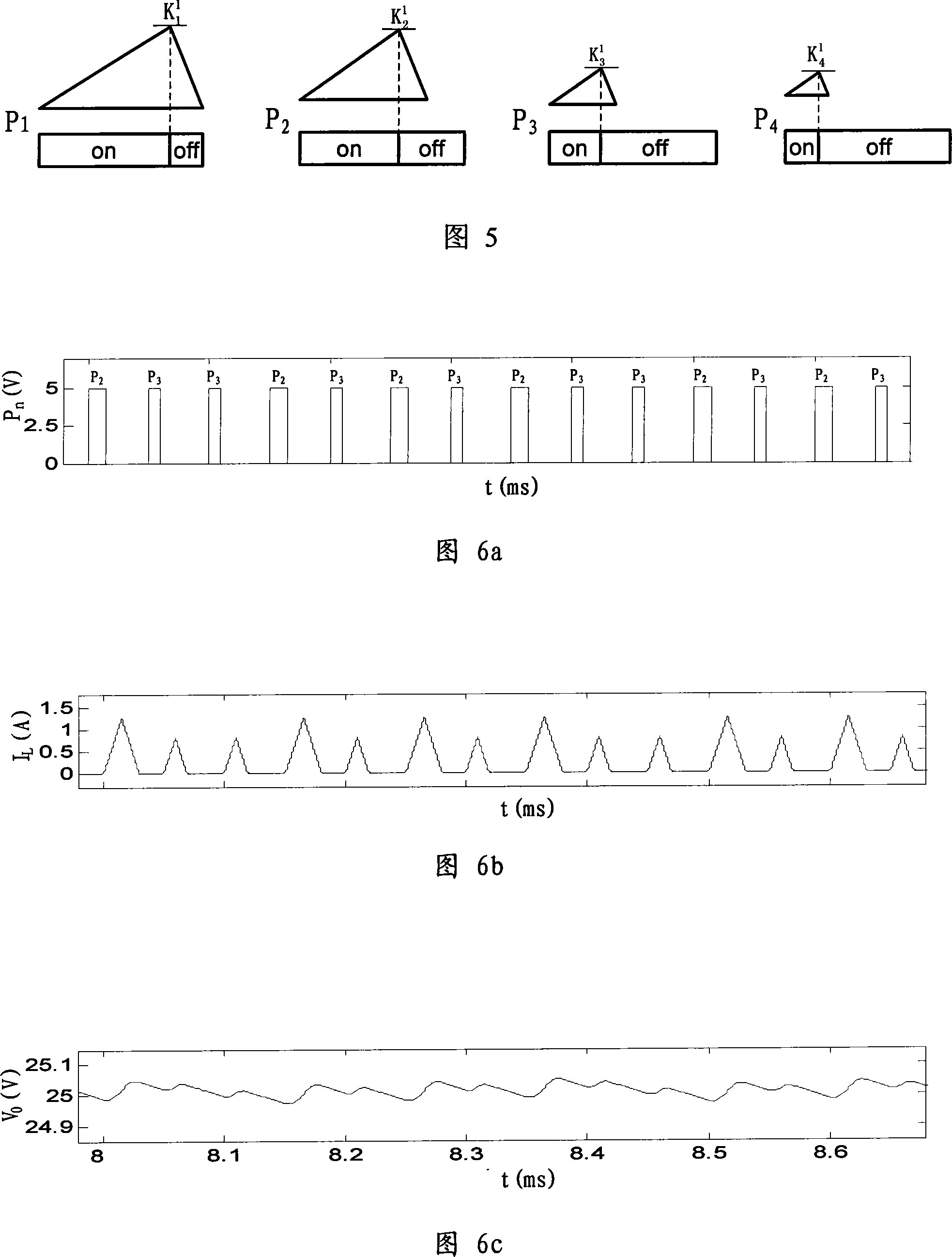
[0051] The voltage detection circuit VCC detects the output voltage V of the converter TD 0 , the error amplifier VA uses the output reference voltage V at the beginning of each switching cycle ref with the output voltage V 0 The error voltage value ΔV is generated by comparison; the error interval judger VC compares the error voltage value ΔV with the set N=3 output voltage error interval value δ n , n=1, 2, 3, for comparison, output corresponding control pulse selection signals to the multi-level pulse generator MPG according to the comparison results, the comparison and selection rules are: when ΔV>δ 1 When , the output signal of the error interval judge VC makes the multi-level pulse generator MPG generate the control pulse P with the largest duty cycle 1 ; when δ 1 ≥ΔV>δ 2 When , the output signal makes the multi-sta...

Embodiment 2

[0069] Figure 9 shows that this example is basically the same as the first example, the difference is that the number N of error interval values ​​of the set output voltage is 4, and δ n , n=1, 2, 3, 4, the corresponding control pulse P n is five, namely P 1 ,P 2 ,P 3 ,P 4 ,P 5 . Multi-stage pulse generator MPG generates control pulse P n , the method of n=1, 2, 3, 4, 5 is: the multistage pulse generator MPG outputs a high level to the outside at the beginning of each switching cycle; the sawtooth wave generating circuit SG synchronously generates a cycle equal to the sawtooth of the switching cycle wave signal V SAW , the multi-level pulse generator MPG combines the sawtooth signal with the control pulse P of the period n Corresponding sawtooth wave signal reference value K n 2 , n=1, 2, 3, 4, 5 for comparison, when the sawtooth signal V SAW Rise to the corresponding sawtooth signal reference value K n 2 , the control pulse P n From high level to low level until...

Embodiment 3

[0073] Figure 10 shows that this example is basically the same as the first example, the difference is that: the number N of error interval values ​​of the set output voltage is 5, and δ n , n=1, 2, 3, 4, 5, corresponding to six control pulses P n ,, n=1, 2, 3, 4, 5, 6. Multi-stage pulse generator generates 6 control pulses P n , the method of n=1, 2, 3, 4, 5, 6 is: the multi-level pulse generator MPG outputs a high level to the outside at the beginning of each switching period. The voltage detection circuit VCCE of the equivalent series resistance ESR of the output filter capacitor C in the converter synchronously detects the voltage V on the equivalent series resistance ESR of the output filter capacitor C ESR , the multilevel pulse generator takes the voltage signal V ESR with the period of the control pulse P n The voltage reference value K of the equivalent series resistance ESR of the corresponding output filter capacitor C n 3 , n=1, 2, 3, 4, 5, 6 for comparison, ...


PUM


Abstract

The invention relates to a control method for switching power supply, whose specific practices are as following: a voltage checking electric circuit (VCC) examines the output voltage V<0> of a converter then delivered to an error amplifier (VA), the error amplifier (VA) carries on the comparison with an output reference voltage V and the output voltage V<0> to get an error voltage value delta V at the start time of each switching period; an error interval judgment (VC) compares the error voltage value delta V with error interval delta n, n=1,2,... N (N=2-5) of the output voltage, control pulse selection signals are outputted to cause a multistage pulse generator (MPG) to generate multistage control pulse with different dutyfactors according to the comparison result, so that the switch tube (TD)of the converter is carried on multistage control. When using the control method, the output voltage ripple of the converter is small, the dynamic response is good, anti-interference capability is strong, and the method is suitable for converters of various topologies.

Description

technical field [0001] The invention relates to a control method and device for a switching power supply. Background technique [0002] In recent years, power electronics technology has developed rapidly, and power supply technology, which is an important part of the field of power electronics, has become a hot spot in application and research. With the advancement of power electronic device manufacturing technology and converter technology, switching power supply has established its mainstream position in DC-DC conversion. Computers, communication equipment, electronic testing equipment, control equipment, etc. are widely used switching power supply as a power supply device. The switching power supply is mainly composed of two parts, the converter and the controller. Converters are also called power circuits, mainly including switching devices, transformer devices and rectification and filtering circuits; converters have Buck, Boost, forward, flyback and other topological...

Claims


Application Information

Patent Timeline
IPC IPC(8): H02M1/08H02M3/155H02M3/157H02M3/335
Inventor 许建平秦明
Owner SOUTHWEST JIAOTONG UNIV
Why Eureka
Try Eureka