
Method for plaiting a fibre web control device and textile machine combination

A control device, fiber strip technology, applied in fiber processing, fiber feeding, textile and papermaking, etc., can solve the problem of unreliable prevention of knot structure, etc., to prevent the formation of knot structure and defective drafting. Effect

Inactive Publication Date: 2008-08-13
MASCHINENFABRIK RIETER AG
View PDF2 Cites 5 Cited by
  • Summary
  • Abstract
  • Description
  • Claims
  • Application Information

AI Technical Summary

Problems solved by technology

As a result, knot formations and defective drafting cannot be reliably prevented by means of the disclosed device

Method used


Image

  • Method for plaiting a fibre web control device and textile machine combination
  • Method for plaiting a fibre web control device and textile machine combination
  • Method for plaiting a fibre web control device and textile machine combination

Examples


Embodiment Construction

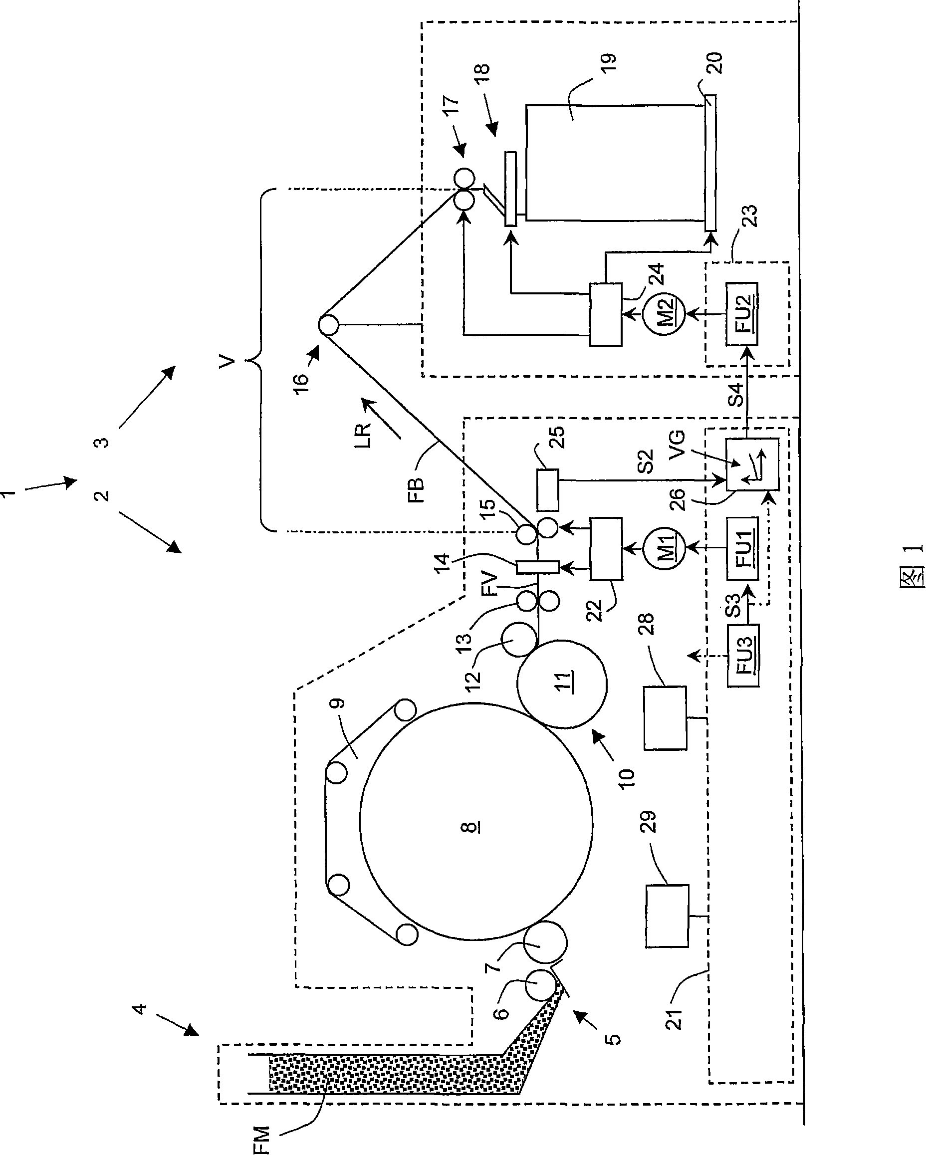
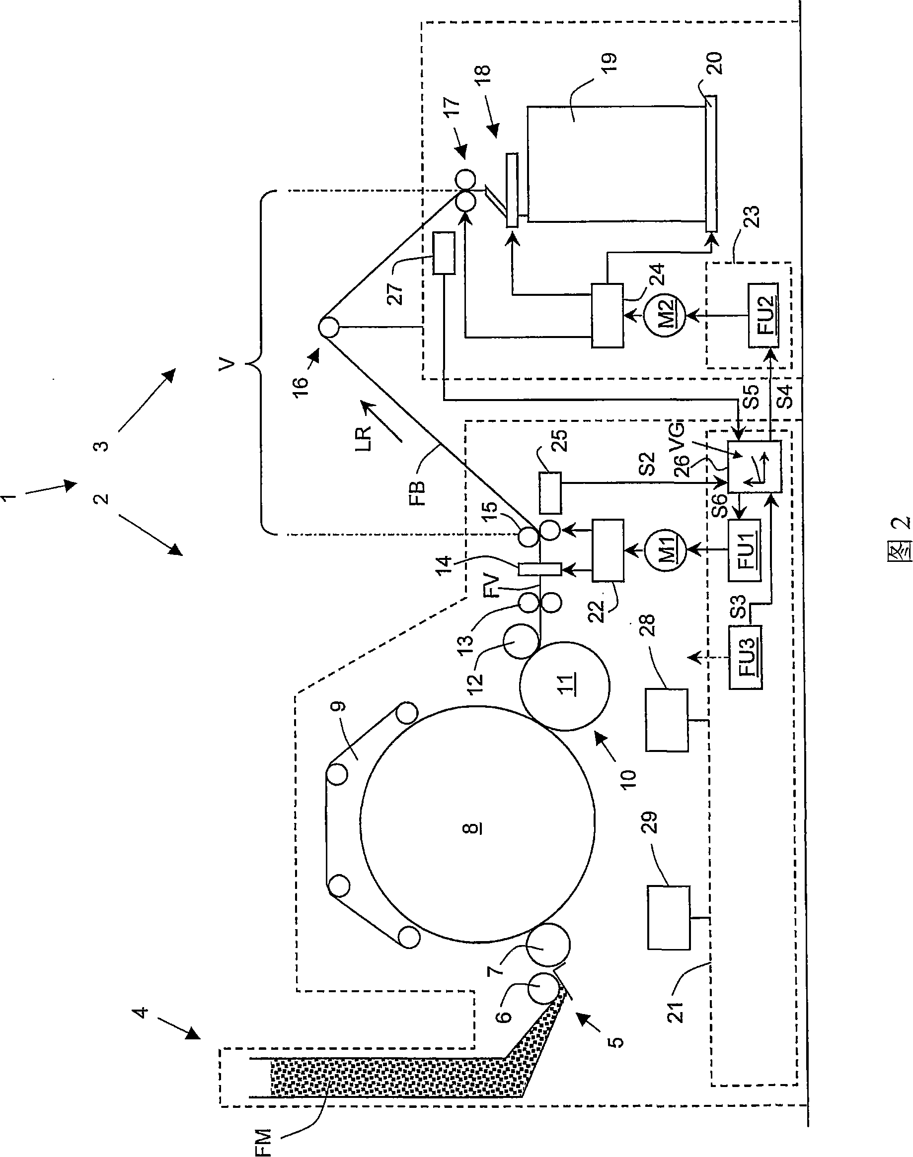
[0044] FIG. 1 shows a spinning machine 1 comprising a spinning preparation machine 2 delivering a fiber sliver and a fiber sliver depositing device 3 . A card (Karde) 2 is shown here as an example of a spinning preparation machine 2 that delivers the fiber sliver. However, the present invention can also be applied to any spinning machine 1 that contains another spinning preparation machine 2 that outputs the fiber sliver, which can be, for example, a carding machine (Krempel), a spinning preparation machine 2 Drawing frame or combing frame.

[0045] The carding machine 2 is provided for carding synthetic or natural fibers, in particular staple fibers, and fiber mixtures formed therefrom. The card 2 comprises a feed trough 4 which is only schematically shown here. This feed trough 4 comprises in its upper part a feeding chute and in its lower part a storage trough in a known manner, with an opener device interposed therebetween, said opener device comprising, for example, a g...


PUM


Abstract

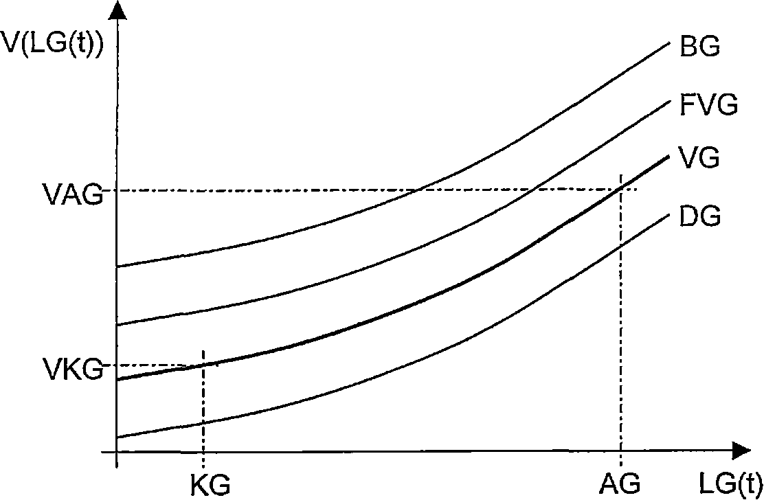
The invention discloses a method for placing a fiber sliver (FB) output by a spinning preparation machine (2), such as a carding machine (2), combing machine or drafting machine, by means of The fiber sliver (FB) is placed in the fiber sliver container (19) at the fiber sliver placement device (3), wherein the fiber sliver (FB) runs from the output device (15) located at the outlet of the spinning preparation machine (2) to the drawing-in device (17) at the entrance of the sliver depositing device (3) and thus undergoes a draft (V) corresponding to the drawing-in speed and output of the drawing-in device (17) The ratio of the output speed (LG) of the device (15). During the placement of the fiber sliver (FB), said draft (V) is automatically and variably controlled by means of a previously defined standard function (VG), which control depends on the output speed of the output device (15) ( LG). The invention also discloses a control device (26) for implementing the above method and a textile machine combination (1) with the control device (26).

Description

technical field [0001] The invention relates to a method for depositing a sliver delivered by a spinning preparation machine into a sliver container by means of a sliver depositing device, wherein the sliver is taken from a delivery device located at the outlet of the spinning preparation machine into a sliver container. The transfer is into a draw-in device located at the entrance of the sliver depositing device and is thus subject to a draft proportional to the draw-in speed of the draw-in device and the output speed of the output device. [0002] In another aspect, the invention relates to a control device for drafting a sliver output from a spinning preparation machine to a sliver depositing device, at the output device at the outlet of the spinning preparation machine and at the inlet of the sliver depositing device. The draft is experienced between the pull-in devices at , wherein the draft is proportional to the pull-in speed of the pull-in device and the output speed o...

Claims


Application Information

Patent Timeline
Patent Type & Authority Applications(China)
IPC IPC(8): D01G23/06B65H54/80
CPCD01G23/06B65H54/80B65H2701/31
Inventor 托马斯·布罗泽格茨·特奥多尔·格雷塞尔克里斯蒂安·米勒
Owner MASCHINENFABRIK RIETER AG
Learn More