Fluid control apparatus

A technology of a fluid control device and a fluid control valve, which is applied in the direction of fluid pressure control, valve device, and flow control of an electrical device, and can solve problems such as errors, complexity, and damage to the driver control valve 308

Inactive Publication Date: 2008-08-13
ASAHI YUKIZAI KOGYO CO LTD
View PDF7 Cites 12 Cited by
  • Summary
  • Abstract
  • Description
  • Claims
  • Application Information

AI Technical Summary

Problems solved by technology

[0005] However, the above-mentioned existing pure water flow control device 301 balances the output pressure of the pure water in the flow regulating valve 302, thereby controlling the pure water flow output from the flow regulating valve 302 to be constant. Therefore, It cannot be used to finely control the flow rate, and the flow range is not wide enough, so there is a problem that it is difficult to control the flow rate in a wide flow range
In addition, since there are multiple components, when installing them in semiconductor manufacturing equipment, etc., it is necessary to perform piping connection work, electrical wiring, and air piping work for each component separately. The work is complicated and time-consuming, and the piping and wiring may be complicated. error occurred
[0006] In addition, for the above-mentioned existing flow control module 306, when the fluid flowing into the fluid control device is a pulsating fluid with a short pressure fluctuation period, the control valve 308 operates to control the flow of the pulsating fluid, but there are fluctuations, The problem of not being able to control the flow rate, if it still persists, there is also a problem that the driver 311 and the control valve 308 may be damaged
In addition, since the flow rate range for flow control is not wide, there is a problem that it is difficult to use it for the purpose of controlling the flow rate in a large flow rate range.

Method used


Image

  • Fluid control apparatus
  • Fluid control apparatus
  • Fluid control apparatus

Examples


Embodiment 1

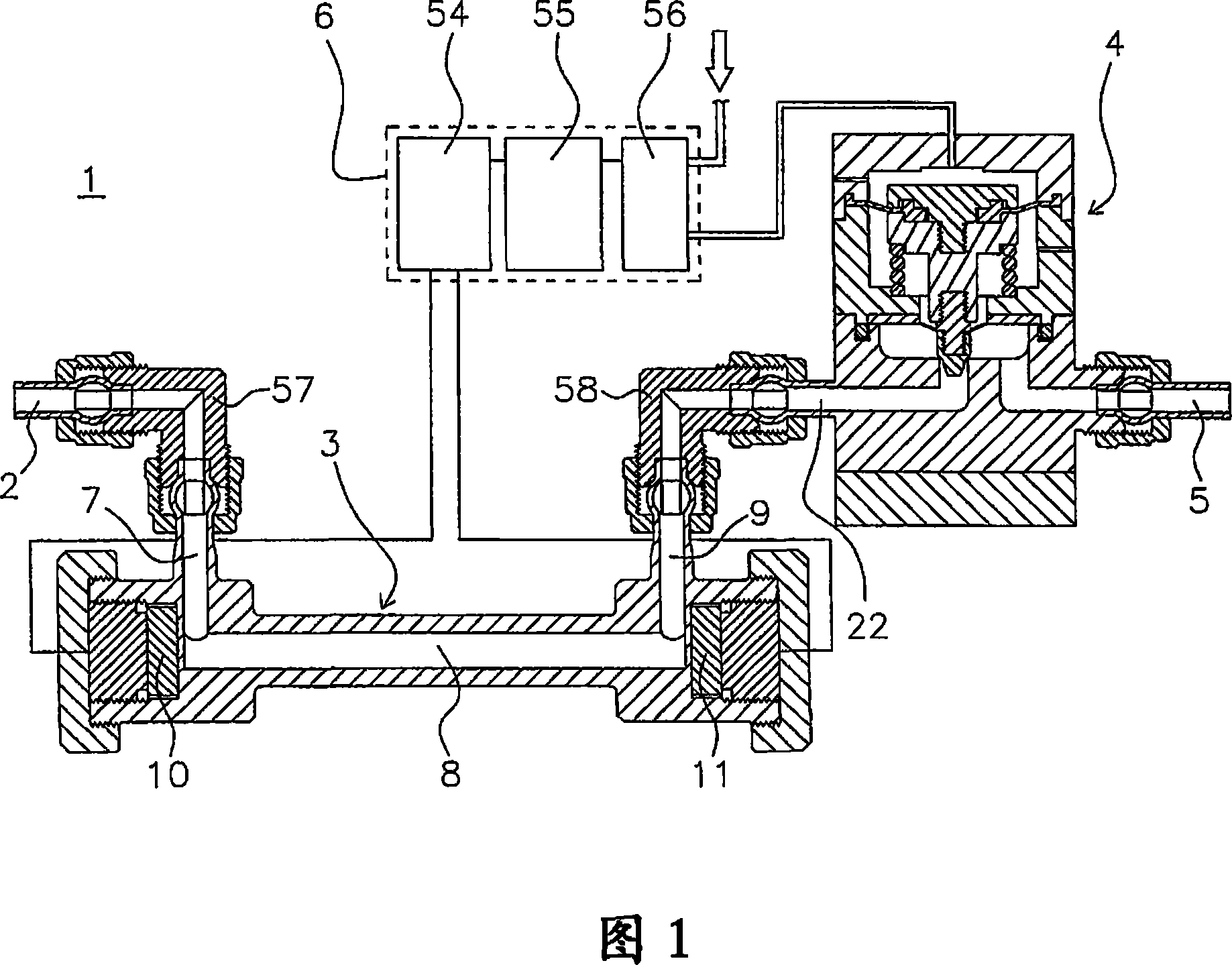
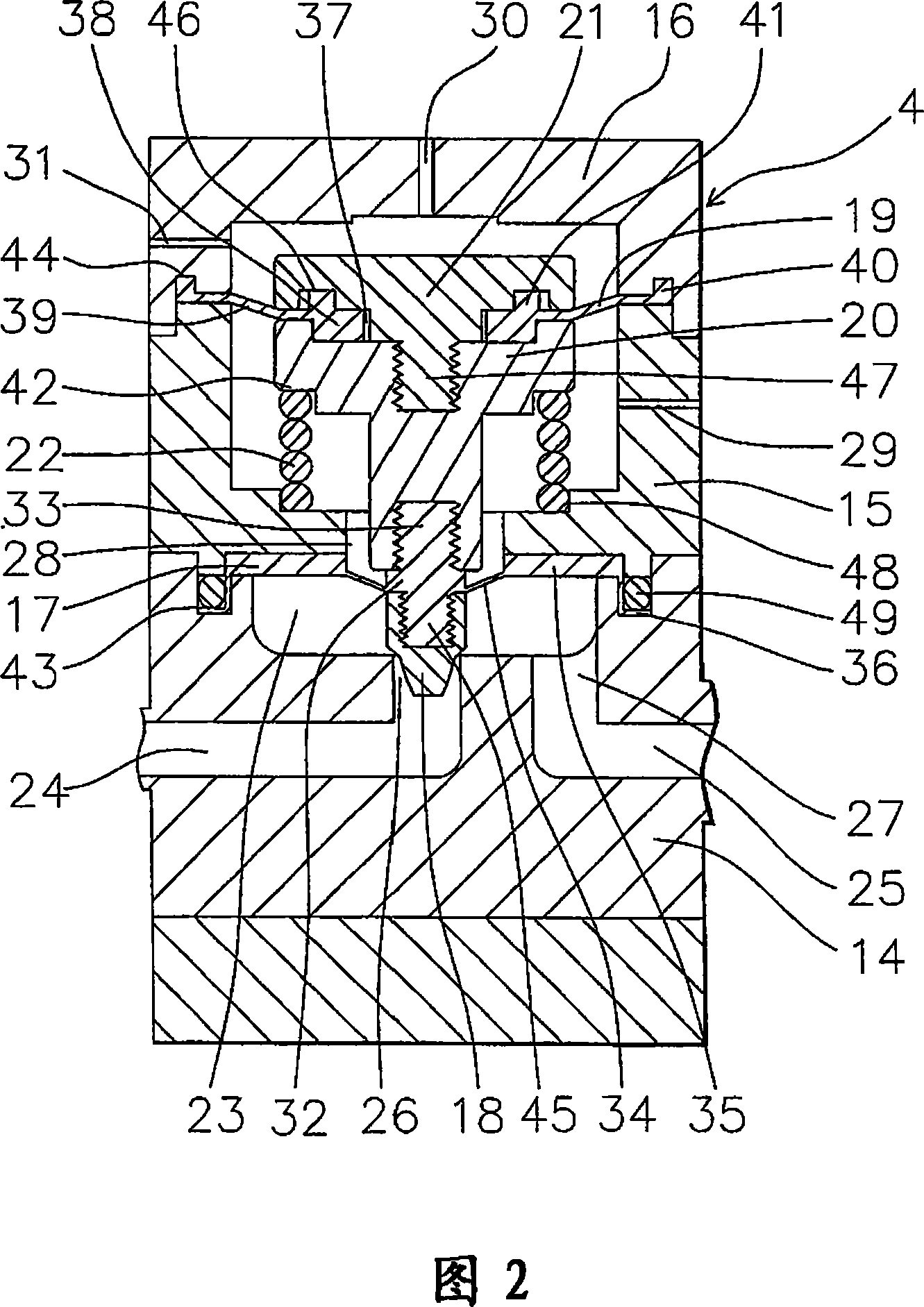
[0076] Hereinafter, a fluid control device according to a first embodiment of the present invention will be described based on FIGS. 1 and 2 .

[0077] Reference numeral 1 denotes a fluid control device installed in a semiconductor manufacturing device that performs an etching process in semiconductor manufacturing. The fluid control device 1 is formed of a fluid inlet 2, a flow meter 3, a fluid control valve 4, a fluid outlet 5, and a control unit 6, and their respective structures are as follows.

[0078] 2 is a fluid inlet made of PFA. The fluid inflow port 2 communicates with an inlet channel 7 of a flow meter 3 described later.

[0079] 3 is a flow meter for measuring the flow rate of a fluid. The flow measuring device 3 has: an inlet flow path 7, a straight flow path 8 vertically arranged from the inlet flow path 7, and an outlet flow path 9 vertically arranged from the straight flow path 8 and parallel to the inlet flow path in the same direction, Ultrasonic vibrator...

Embodiment 2

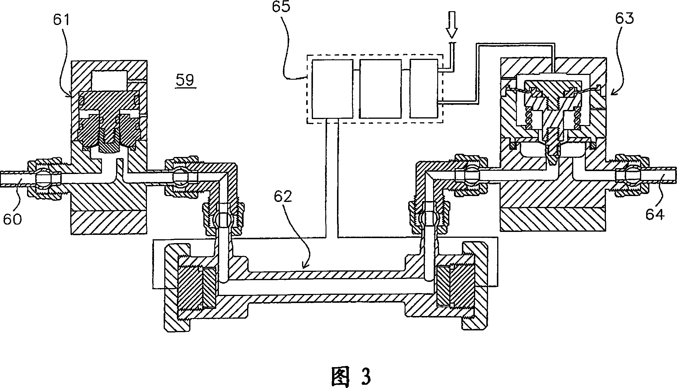
[0103] Next, a fluid control device which is a second embodiment of the present invention will be described based on FIGS. 3 and 4 .

[0104] As shown in FIG. 3, the fluid control device 59 is composed of a fluid inlet 60, an on-off valve 61, a flow meter 62, a fluid control valve 63, a fluid outlet 64, and a control unit 65. The respective structures are as follows .

[0105] As shown in FIG. 4 , the on-off valve 61 is formed of a main body 66 , a drive portion 67 , a piston 68 , a diaphragm retainer 69 , and a valve body 70 .

[0106] 66 is a main body made of PTEF, with a valve chamber 71 in the center of the upper end in the axial direction, an inlet flow path 72 and an outlet flow path 73 communicating with the valve chamber 71, the inlet flow path 72 communicates with the fluid inlet 60, and the outlet flow path 73 communicates with the fluid inlet The flow meter 62 communicates. In addition, an annular groove 74 is provided on the upper surface of the main body 66 out...

Embodiment 3

[0117] Next, a fluid control device according to a third embodiment of the present invention will be described based on FIGS. 5 and 6 .

[0118] As shown in FIG. 5, the fluid control device 81 is composed of a fluid inlet 82, a pressure regulating valve 83, a flow meter 84, a fluid control valve 85, a fluid outlet 86, and a control unit 87. The respective structures are as follows. .

[0119] As shown in FIG. 6 , 83 is a pressure regulating valve for attenuating pressure fluctuation of fluid.

[0120] The pressure regulating valve 83 is formed of a main body 12w, a valve cover 13w, a spring seat 14w, a piston 15w, a spring 16w, a first valve mechanism body 17w, a second valve mechanism body 18w, and a base member 19w.

[0121] 12w is a main body made of PTFE, which has a second void 20w opened from the center of the lower part to the bottom, and a first void 21w opened to the upper surface from the upper part and has a larger diameter than the second void 20w. An inlet chann...


PUM


Abstract

The fluid control device according to the present invention is characterized by comprising: a fluid control valve that controls the flow rate of the fluid by changing the opening area of ​​the flow channel; a flow measuring device that converts and outputs an electrical signal; and a control unit that controls the opening area of ​​the fluid control valve based on the deviation between the electrical signal from the flow measuring device and a set flow rate The command signal is output to the fluid control valve or the device that operates the fluid control valve.

Description

technical field [0001] The present invention relates to a fluid control device used in fluid transfer piping that requires fluid control. More specifically, it is mainly related to easy installation, piping and wiring connection in semiconductor manufacturing equipment, flow control can be performed without problems even if pulsating fluid flows, and stable and high-precision accuracy can be achieved in a large flow range. A fluid control device for flow control. Background technique [0002] Conventionally, as one of the semiconductor manufacturing processes, wet etching is used to etch the surface of a wafer using cleaning water obtained by diluting a chemical solution such as hydrofluoric acid with pure water. The concentration of cleaning water for these wet etching must be managed with high precision. In recent years, the method of controlling the concentration of cleaning water based on the flow rate ratio of pure water and chemical solution has become mainstream. Th...

Claims


Application Information

Patent Timeline
Patent Type & Authority Applications(China)
IPC IPC(8): G05D7/06F16K1/32F16K7/06F16K7/07F16K31/04F16K41/12
CPCF16K7/045F16K7/07F16K31/1221F16K41/103G05D16/185Y10T137/8158F16K7/06H01L21/02
Inventor 吉野研郎山本崇
Owner ASAHI YUKIZAI KOGYO CO LTD
Why Eureka
Try Eureka