Breathing machine and pressure control method

A ventilator and pressure technology, which is applied in the field of ventilators, can solve the problems of patient airway collapse, ventilator pressure control, and large airway resistance, and achieve the effects of flexible adjustment of output pressure, guaranteed use effect, and unobstructed airway

Inactive Publication Date: 2008-08-20
CURATIVE MEDICAL TECH INC
View PDF0 Cites 40 Cited by
  • Summary
  • Abstract
  • Description
  • Claims
  • Application Information

AI Technical Summary

Problems solved by technology

If the patient has not fallen asleep after the set delay time, the higher therapeutic pressure will make the patient less tolerable; if the patient falls asleep earlier, the patient may experience airway collapse or hypoventilation because the pressure has not yet reached the therapeutic pressure. Did not achieve therapeutic effect
In addition, since this method reaches the preset time, the therapeutic pressure output by the ventilator will be higher for awake patients, causing discomfort, and it will also cause a certain psychological burden for some patients to fall asleep, affecting normal sleep.
[0015] (2) The disadvantages of AutoCPAP are as follows: ① During the whole sleep process, due to the frequent changes in airway resistance, the patient continuously increases and decompresses the pressure, resulting in more pressure fluctuations and affecting sleep quality
② Inadequate treatment
In this way, especially for heavier patients, the cumulative time for patients with greater airway resistance during treatment will be more
In addition, the current method for judging airway resistance is still insufficient to a certain extent. During AutoCPAP therapy, some patients often suffer from hypoventilation.
[0016] In summary, due to the inability of the existing ventilator to perform accurate pressure control, it cannot fully meet the requirements for the treatment of sleep apnea hypopnea syndrome

Method used


Image

  • Breathing machine and pressure control method
  • Breathing machine and pressure control method
  • Breathing machine and pressure control method

Examples


Embodiment 1

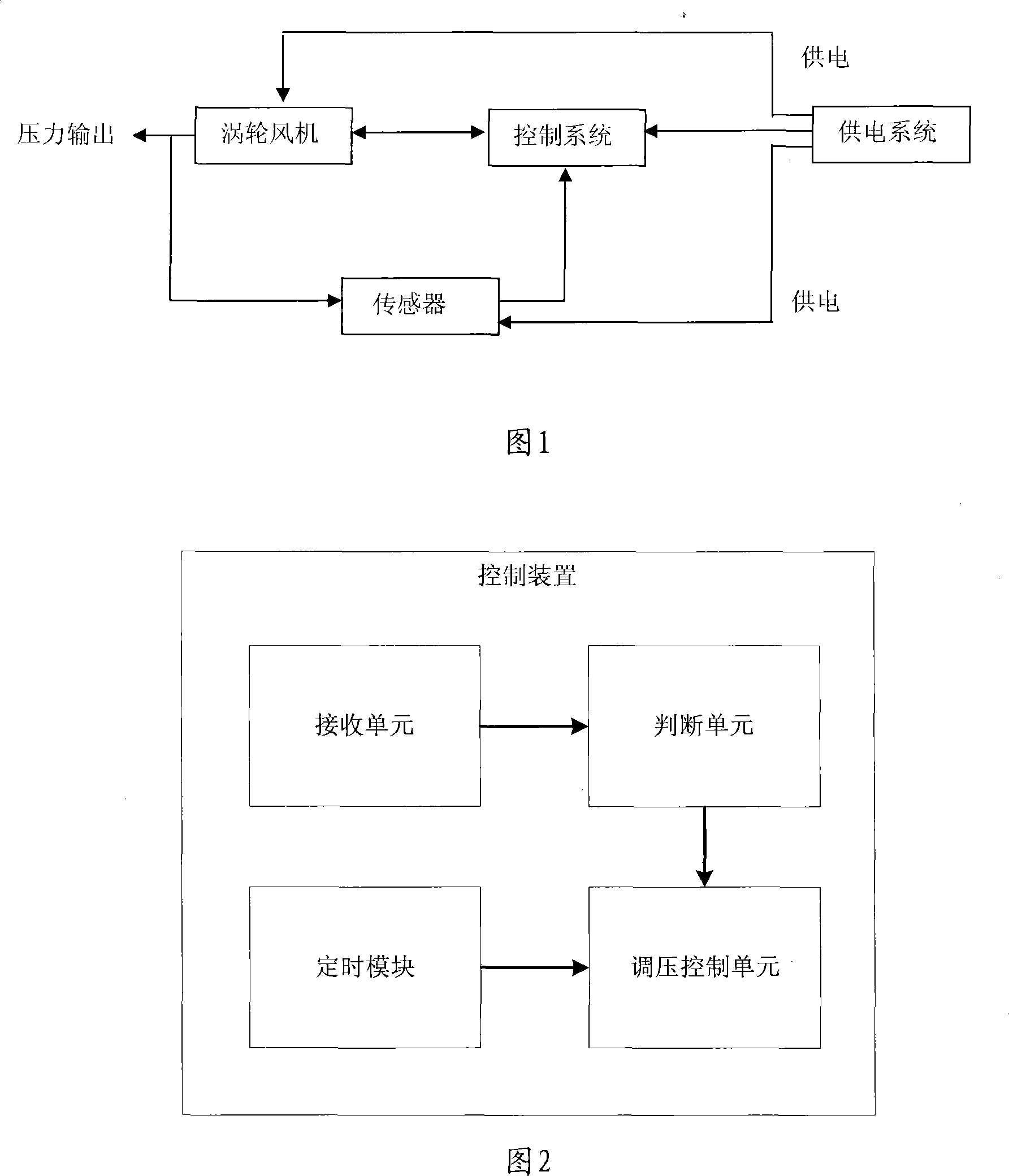
[0052] As shown in Figure 1, the embodiment of the present invention provides a ventilator, including a casing, inside the casing is set: a turbo blower for generating and outputting wind with a certain pressure; connected with the turbo blower to control the operation of the turbo blower The control device; the sensor arranged at the pressure output end of the turbo blower, the signal feedback end of the sensor is connected with the control device; the power supply device is respectively connected with the turbo blower, the control device, the sensor and other components to supply power to them.

[0053]Wherein, the sensors include: pressure sensors and / or flow sensors. Different sensors can be set according to the needs of ventilator performance during preparation. When producing high-end ventilators, pressure sensors and flow sensors can be installed in the machine at the same time to make it have better performance. When producing low-end ventilators Only the pressure sens...

Embodiment 2

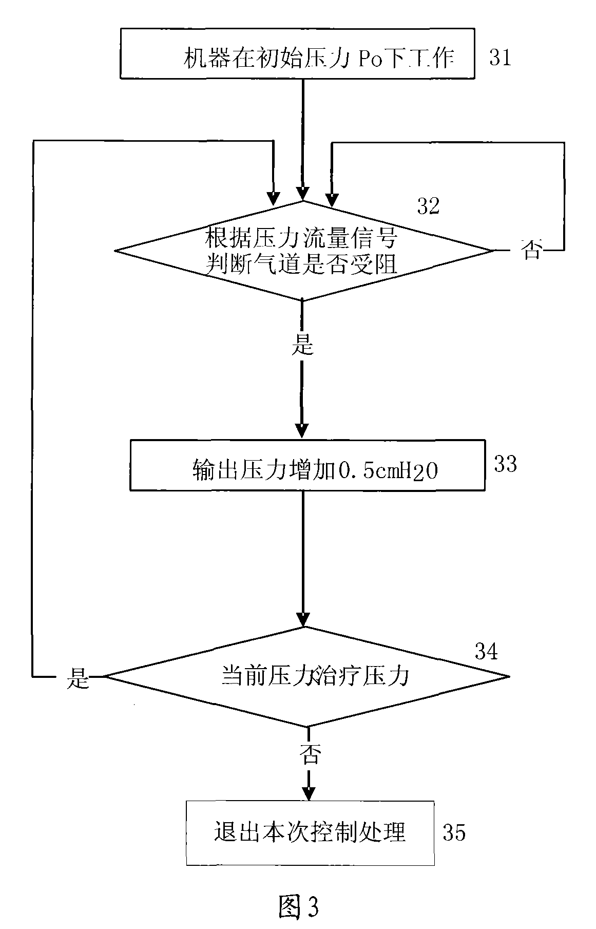
[0060] The embodiment of the present invention also provides a ventilator pressure control method, the pressure control method mainly judges the change of the airway resistance of the ventilator user through the feedback signal provided by the sensor. Generally, when the user is not falling asleep, the airway resistance is small, and only a low base pressure needs to be provided. At this time, the user will be more comfortable, which is conducive to falling asleep freely. When the user falls asleep, the airway resistance may increase in stages. Use the signal fed back by the sensor to judge this, and control the pressure of the ventilator to increase appropriately, and under appropriate conditions, the output pressure of the ventilator reaches Treat stress. Its process includes:

[0061] Adopt the ventilator described in embodiment one; This ventilator works under the initial pressure state;

[0062] The ventilator judges whether the airway is blocked by the pressure / flow s...

Embodiment 3

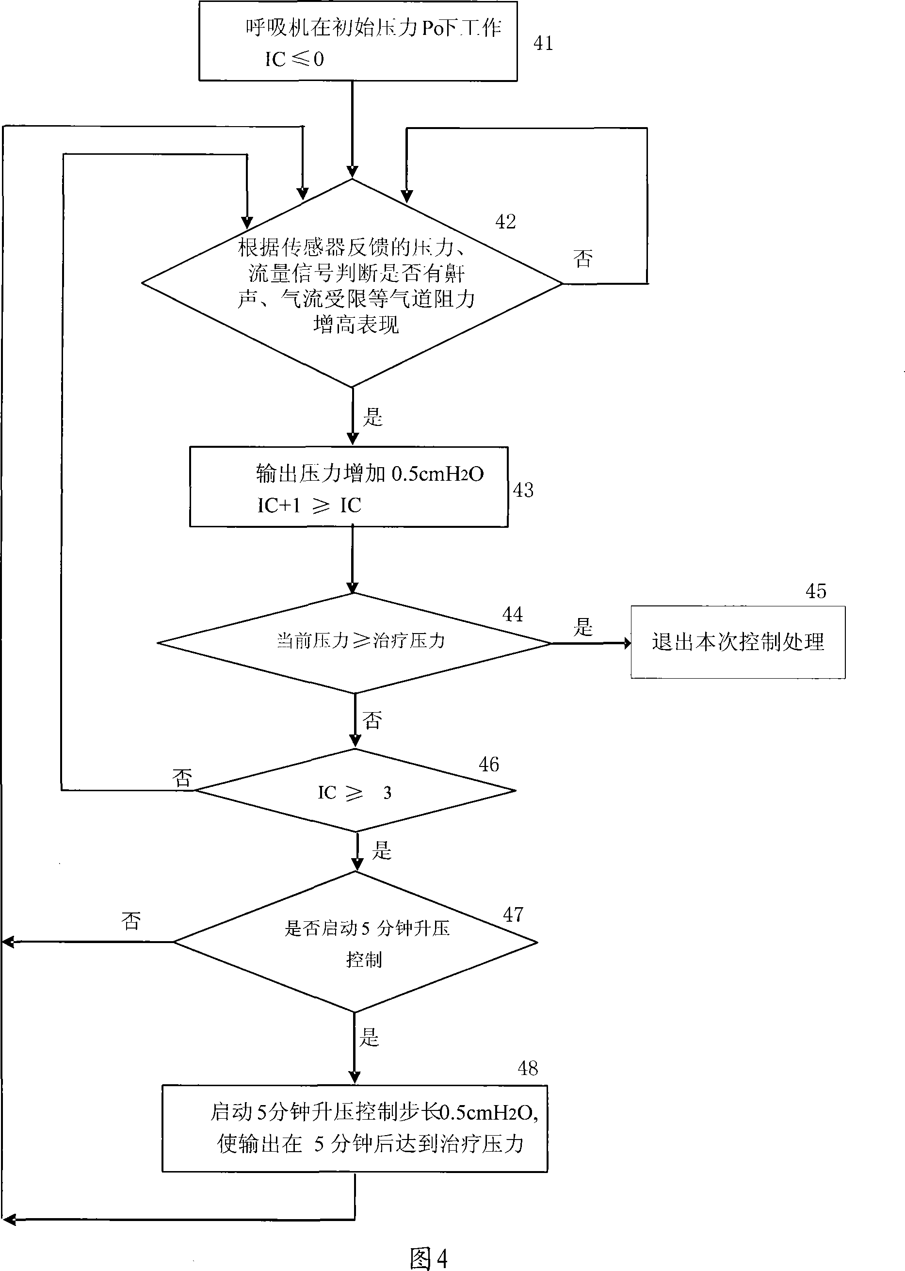
[0078] As shown in Figure 4, the embodiment of the present invention also provides another pressure control method of the ventilator. After the output pressure has been boosted N times, if the treatment pressure is not reached, the pressure is gradually increased within the specified time m minutes. Rise to therapeutic pressure. Or pressurize according to the increase of airway resistance until the set working pressure is reached. Increase the pressure until the phenomenon of large airway resistance disappears, as follows:

[0079] In order to express more clearly, the initial working pressure of the ventilator is set as P0, the number of pressurization is set as IC, the treatment pressure is set as P, and the current pressure is set as Pt;

[0080] Step 41, the ventilator works under the initial pressure P0, and the current pressurization times are 0;

[0081] Step 42, judging whether there are signs of increased airway resistance such as snoring and airflow obstruction acc...


PUM


Abstract

The invention discloses a ventilator and pressure control method, comprising a casing, a turbine fan, a control device, a sensor, and a power supply device; wherein, the turbine fan is used for producing and outputting wind with certain pressure; the control device is connected with the turbine fan to control the operation of the turbine fan; the sensor is positioned at the pressure output end of the turbine fan; wherein, the feedback end of the sensor is connected with the control device; the power supply device is connected with each part for power supply; which is characterized in that: the pressure / flow rate is detected by the sensor, so that the control device can control the turbine fan according to the feedback of the sensor, and the ventilator can provide different output pressure when the user is under different breathing condition; by monitoring the resistance in the air passage during the sleeping process of the user, pressure can be raised according to need, so that the user will not feel uncomfortable. The ventilator has the advantages of simple structure, flexibility of regulating output pressure and ensured application effect.

Description

technical field [0001] The invention relates to a ventilator technology, in particular to a ventilator and a pressure control method for maintaining smooth breathing of patients with respiratory disorders in a sleeping state. Background technique [0002] At present, with the improvement of people's awareness of various diseases caused by poor breathing (such as snoring, etc.), the use of ventilators is becoming more and more popular. The ventilator is an artificial mechanical ventilation device, which is used to assist or control the patient's spontaneous breathing movement, so as to achieve the function of gas exchange in the lungs, reduce the consumption of the human body, and facilitate the recovery of respiratory function. [0003] The basic working principle of the ventilator is to use the pressure difference of the gas to work. According to the application, it can be divided into two categories, one is used to treat diseases of the respiratory system, and the other i...

Claims


Application Information

Patent Timeline
Patent Type & Authority Applications(China)
IPC IPC(8): A61M16/00G05D16/00
Inventor 王鸿庆
Owner CURATIVE MEDICAL TECH INC
Why Eureka
Try Eureka