Process for manufacturing medial wall concave block in LZC oil sump

A manufacturing method and oil pan technology are applied to the manufacturing field of inner side wall concave blocks, which can solve the problems of increasing the labor intensity of operators, slow die-casting rhythm, and inability to fall off, and achieve stable and reliable product quality, good production safety, and production efficiency. Efficiency improvement effect

Inactive Publication Date: 2008-08-20
SHANGHAI HUIDA MFG
View PDF0 Cites 2 Cited by
  • Summary
  • Abstract
  • Description
  • Claims
  • Application Information

AI Technical Summary

Problems solved by technology

This concave block is at the bottom of the inside of the part, the inside is large and the outside is small, and the shape of this concave block is complex, the slider is easy to get stuck and cannot fall off, the risk will be very high
Another difficulty is that the molten aluminum will produce flash during die-casting. The generation of flash is related to the temperature and fluctuation range of the mold, the casting temperature of the molten aluminum, the injection speed and the injection force. The flash enters the inclined top slide The distribution part will cause the inclined top to bite and get stuck
[0003] The existing technology generally adopts the method of inserting blocks. After the die-casting is demoulded, the inserts are removed, and then installed on the mold for the next die-casting. It is also possible to make more inserts, but the die-casting cycle is slow, which increases the labor intensity of the operator. , poor security

Method used


Image

  • Process for manufacturing medial wall concave block in LZC oil sump
  • Process for manufacturing medial wall concave block in LZC oil sump
  • Process for manufacturing medial wall concave block in LZC oil sump

Examples


Embodiment Construction

[0015] Below in conjunction with accompanying drawing and specific embodiment the present invention is described in further detail:

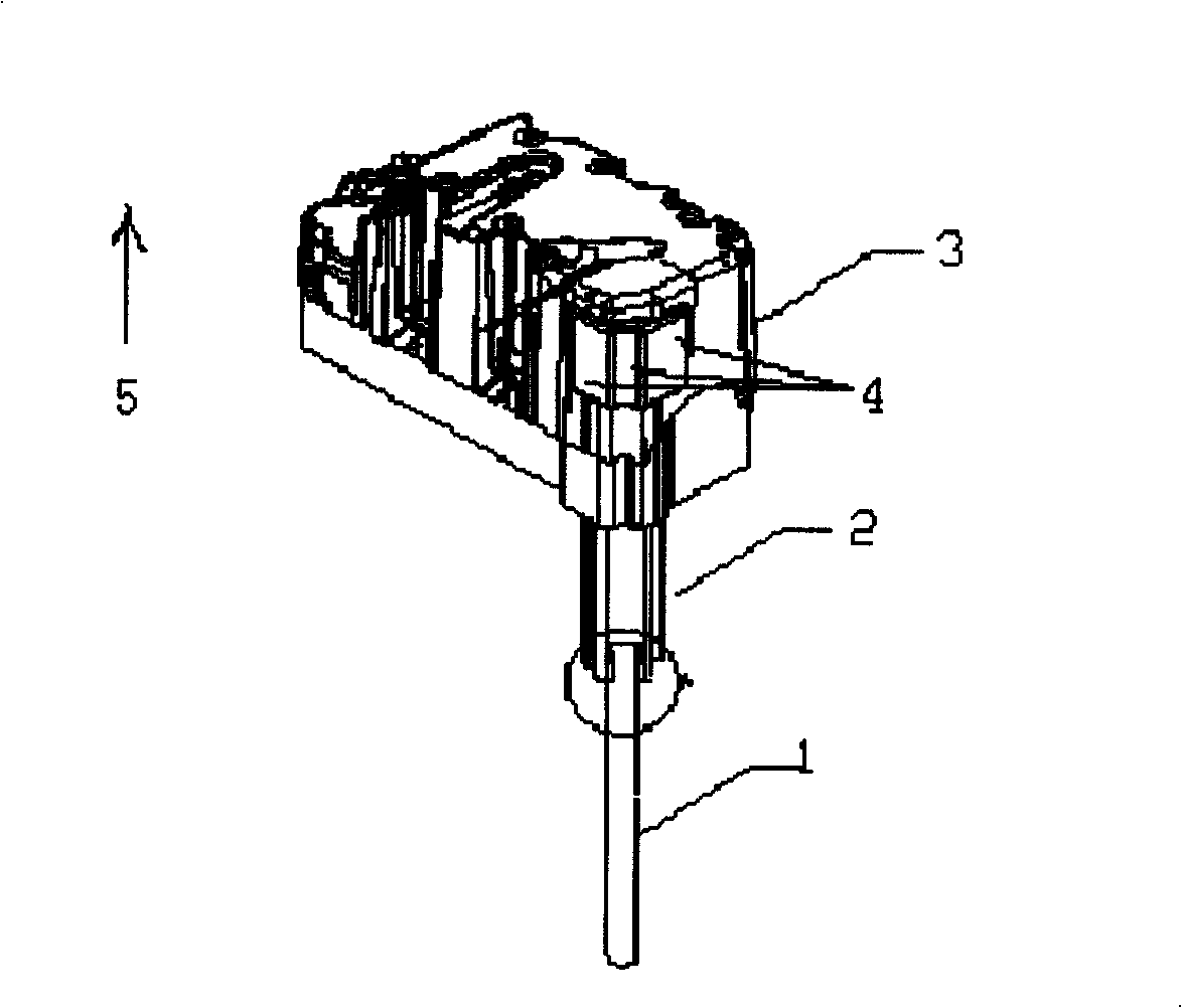
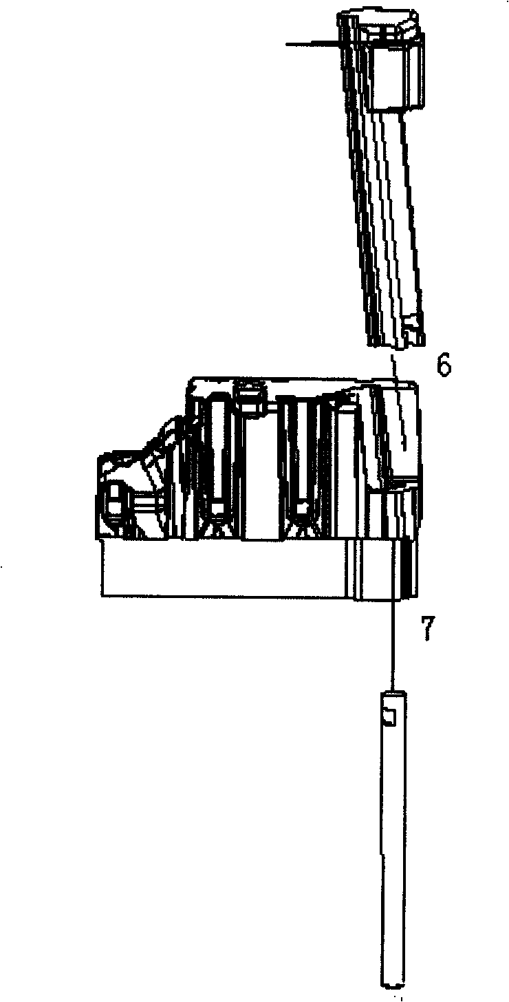
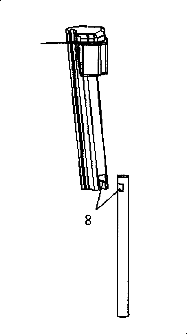
[0016] Depend on figure 1 , figure 2 , image 3 Visible, in figure 1 Middle: push rod 1, inclined top block 2, movable mold insert 3, plane protruding part 4 that causes the barb on the inner wall of the casting at 3, casting direction 5; in figure 2 Middle: downward assembly direction 6, upward assembly direction 7; in image 3 Middle: keyway fit 8.

[0017] When the mold is opened, the push rod is moved vertically upwards by the push plate. Since the top of the push rod 1 is connected with the slanting block 2 by a key, the slanting block 2 will translate to the inside during the rising process to reach the slanting block. When the block exits the barb part of the casting, the casting can be taken out; when the mold is closed, the push rod is moved vertically downward by the push plate, and the inclined top block returns to the original...


PUM


Abstract

The invention relates to a manufacturing process of a concave block arranged on the inner side wall of a LZC oil sump, comprising the following steps: a sloping-roof knockout core is adopted for shortening the contact area of a sloping-roof sliding pair; the four sides of a slider are all provided with slopes; perform a plurality of nitrogen treatments on the sloping-roof surface during die producing process and die casting process; the service temperature of the die is estimated between 150 to 250 degrees centigrade; figure out the clearance of the sloping-roof sliding pair and use the minimum clearance calculation result to produce the sloping-roof sliding pair; adjust and dress the die gradually to obtain a reasonable trimmed value and control the optimal clearance; control the temperature of the sloping-roof sliding pair between 150 to 250 degrees centigrade; control the specific die casting pressure in the die cavity under 850 kilograms per square centimeter; and control the injecting velocity of the ingate under 3.5 meters per second. The method has the advantages that the process of die casting, forming and demoulding is performed automatically; the labor intensity of the operator is reduced; the production safety is good, the product quality is stable and reliable and the productivity is greatly increased.

Description

technical field [0001] The invention relates to a method for manufacturing an LZC oil sump, in particular to a method for manufacturing an inner wall concave block of the oil sump. Background technique [0002] LZC oil pan is a large aluminum alloy die-casting part used in automobile engines. It needs to be produced by die-casting on a 2000T die-casting machine. When designing the workpiece, there must be a concave block on the inner wall of the workpiece. The concave block is at the bottom of the part, the inside is large and the outside is small, and the shape of the concave block is complex, the slider is easy to get stuck and cannot fall off, and the risk will be high. Another difficulty is that the molten aluminum will produce flash during die-casting. The generation of flash is related to the temperature and fluctuation range of the mold, the casting temperature of the molten aluminum, the injection speed and the injection force. The flash enters the inclined top slide...

Claims


Application Information

Patent Timeline
Patent Type & Authority Applications(China)
IPC IPC(8): B22D17/20
Inventor 刘纪纲包家胜
Owner SHANGHAI HUIDA MFG
Why Eureka
Try Eureka