
High-speed area array camera shafting traverse vibration measuring apparatus and method thereof

A technology of measuring device and measuring method, which is applied to the measurement of shafting lateral vibration and the field of measuring device of shafting lateral vibration, which can solve the problems of small spatial measurement range and achieve the effect of low uniformity

Inactive Publication Date: 2008-08-20
HARBIN ENG UNIV
View PDF0 Cites 14 Cited by
  • Summary
  • Abstract
  • Description
  • Claims
  • Application Information

AI Technical Summary

Problems solved by technology

[0003] At present, there are mainly two methods to measure the lateral vibration of the shaft system: eddy current method and laser method. There are such products at home and abroad. The spatial measurement range of this method is small. A set of laser probes can only measure the lateral vibration of a certain point on the shaft at a time vibration

Method used


Image

  • High-speed area array camera shafting traverse vibration measuring apparatus and method thereof
  • High-speed area array camera shafting traverse vibration measuring apparatus and method thereof
  • High-speed area array camera shafting traverse vibration measuring apparatus and method thereof

Examples


Embodiment Construction

[0022] The present invention is described in more detail below in conjunction with accompanying drawing example:

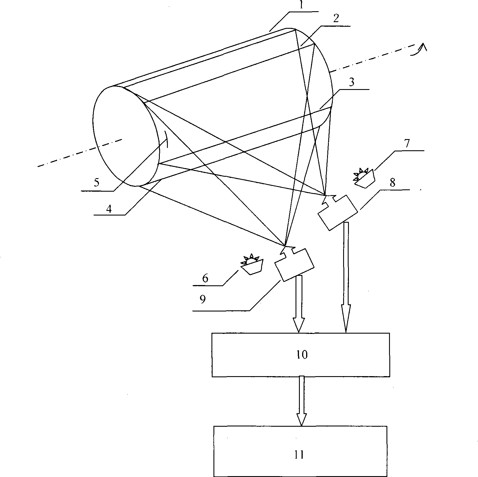
[0023] combine figure 1 , the high-speed area array camera axial vibration measurement device includes: an initial mark (5) arranged in the common field of view of the two high-speed area array cameras on the measured axis, in the same vertical plane, the main optical axes of which are mutually fixed Angle of two high-speed area array cameras, i.e. high-speed area array CCD camera I (8) and high-speed area array CCD camera II (9), and light source I (7) and light source II ( 6), the two high-speed area array cameras are aimed at the same section of the measured axis and roughly parallel to the measured axis, and the two high-speed area array cameras are connected to the data processing and control unit (10) and the human-computer interaction interface (11). The main optical axes of the two high-speed area array cameras form a certain angle with each other within ...


PUM


Abstract

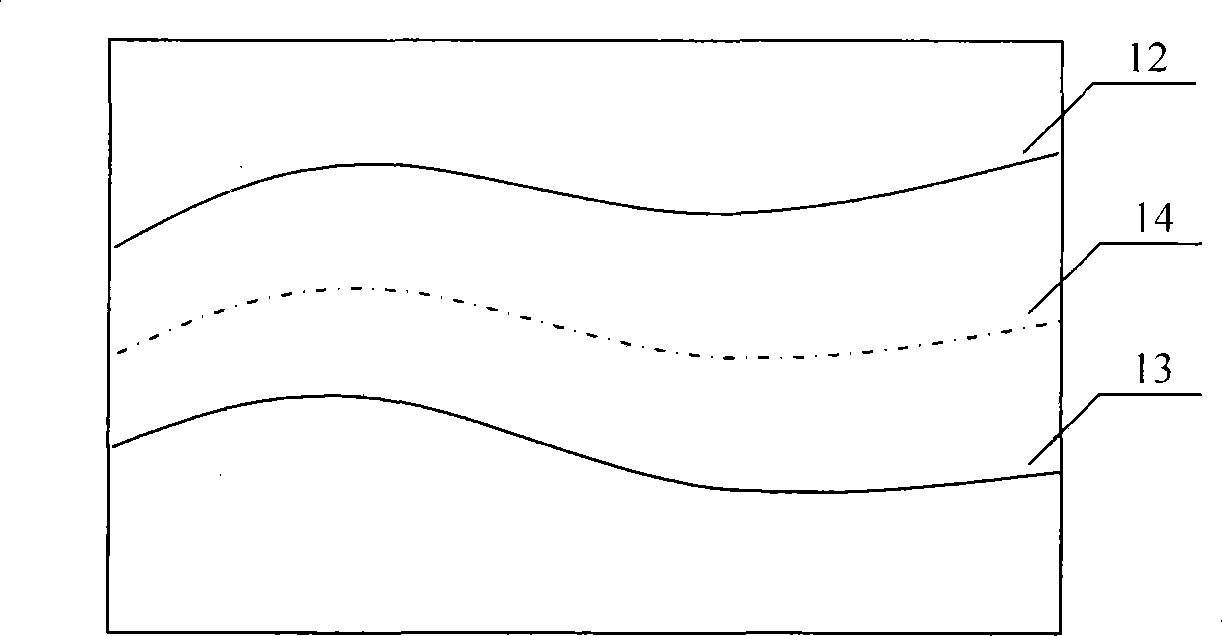
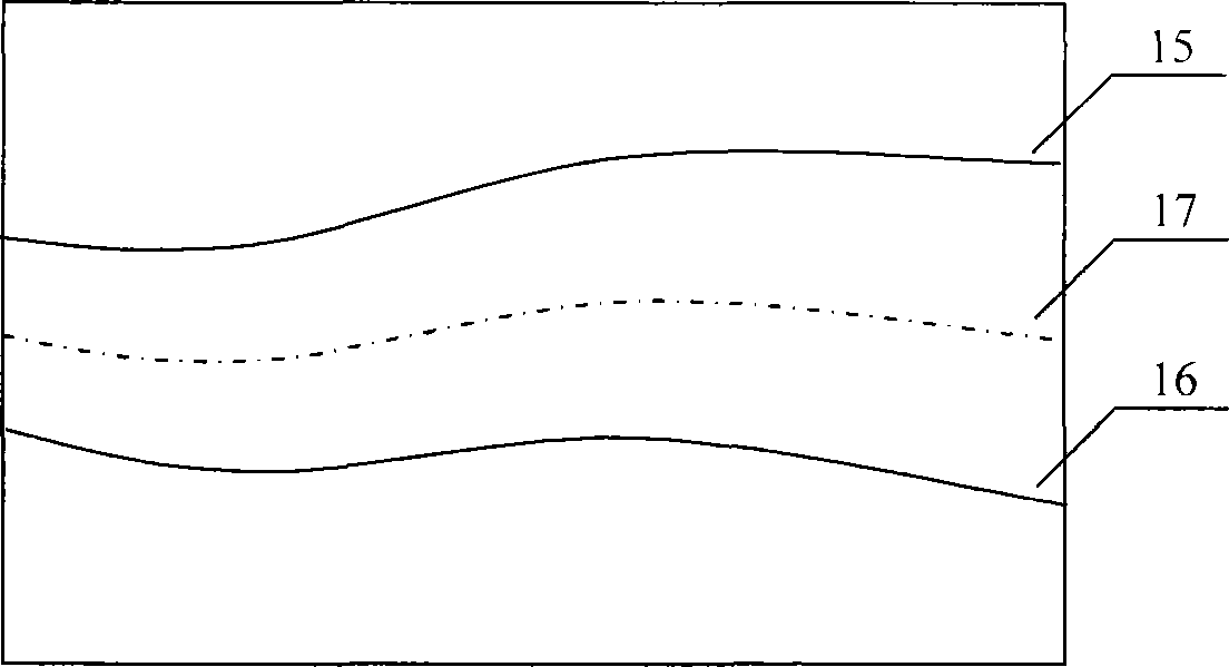
The present invention provides a high-speed area array camera axis system traverse vibration measuring device and the traverse vibration measuring method thereof. The measuring device comprises an initial mark which is arranged on the common visual field of two high-speed area array cameras on the measured axis, two high-speed area array cameras which are arranged in one vertical plane with primary optical axes becoming a certain angle, two high-speed area array cameras are aligned to a same segment of the measured axis and are approximately with the measured axis, and the two high-speed area array cameras is connected to the data processing and control unit and the human-machine interaction interface. When the axis rotates the imaging surface of two high-speed area array cameras respectively catch a group of upper-and-lower edge wires of the measured axis varying continually, and two traverse vibration components at random place of the segment of the measured axis can be obtained by the middle line of the upper-and-lower edge line; and with the method of orthogonal synthesizing the traverse vibration state and axial center track at random place of the segment of the measured axis can be obtained. The invention has the advantages of convenient actualizing, relatively simpler picture signal, no sensitivity to the light intensity or gray scale, no high requirement to the light source and high measurement precision.

Description

(1) Technical field [0001] The invention relates to a vibration testing device for structural components, in particular to a measuring device for shafting lateral vibration. The invention also relates to a method for measuring the lateral vibration of a shaft system. (2) Background technology [0002] All kinds of mechanical shafting, while transmitting torque, will also generate lateral vibration due to the unavoidable unbalanced mass of the shafting and the inevitable gravity of the horizontal shafting. The lateral vibration is the same as the torsional vibration, its additional alternating stress will deteriorate the working condition of the shafting, and have harmful effects on the shafting and the surrounding environment. In order to improve the safety of the shafting operation, it is very important to test, analyze and monitor the lateral vibration of the shafting. [0003] At present, there are mainly two methods to measure the lateral vibration of the shaft system:...

Claims


Application Information

Patent Timeline
IPC IPC(8): G01H9/00G01M7/02G01M13/04
Inventor 温强刘学广黄玉王锋李玩幽张天元王贵强谌东
Owner HARBIN ENG UNIV
Learn More