
Electronic equipment

A technology of electronic equipment and detection electrodes, which is applied in the direction of electrical digital data processing, secondary processing of printed circuits, instruments, etc., can solve problems such as trapped air bubbles, deviation of electrostatic capacitance value, and reduced visual recognition, so as to achieve less detection errors and less static electricity. The effect of less variation in capacitance value and stable capacitance value

Inactive Publication Date: 2008-08-20
ALPS ALPINE CO LTD
View PDF1 Cites 15 Cited by
  • Summary
  • Abstract
  • Description
  • Claims
  • Application Information

AI Technical Summary

Problems solved by technology

Therefore, if a protective sheet is placed on the sensor electrodes, many indeterminate air bubbles will remain in the height difference portion, and as a result, there will be a problem that the capacitance value will vary greatly.
[0009] In addition, in the configuration in which the protective sheet also serves as the display portion of the liquid crystal display device formed in the transparent panel, many bubbles in an indeterminate shape appear around the display portion, resulting in a problem that the visibility decreases when viewed from the outside.

Method used


Image

  • Electronic equipment
  • Electronic equipment
  • Electronic equipment

Examples


Embodiment Construction

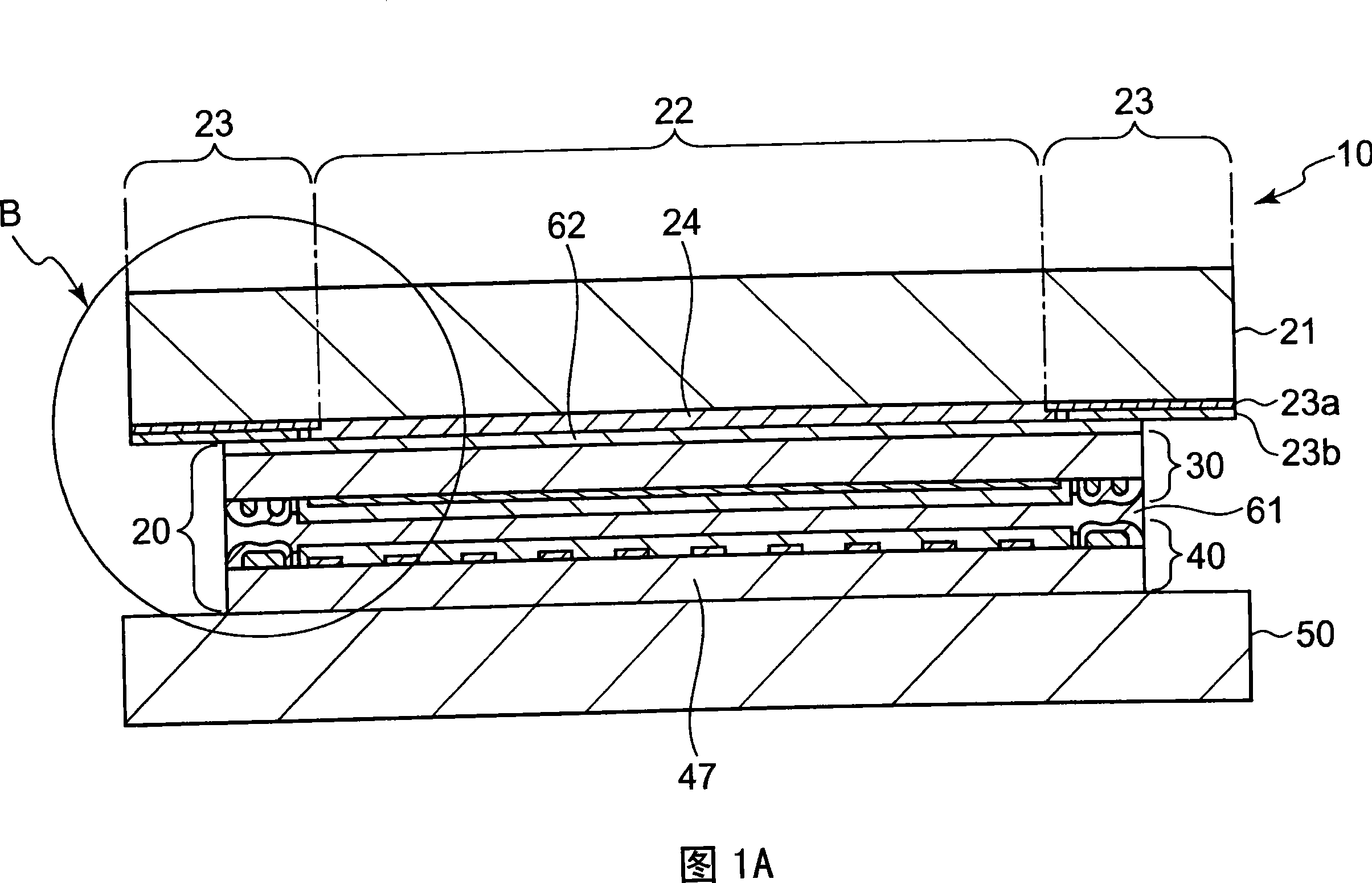
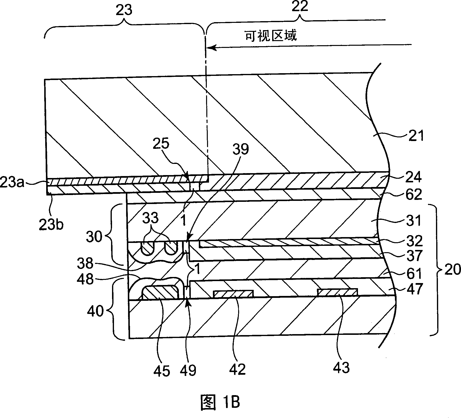
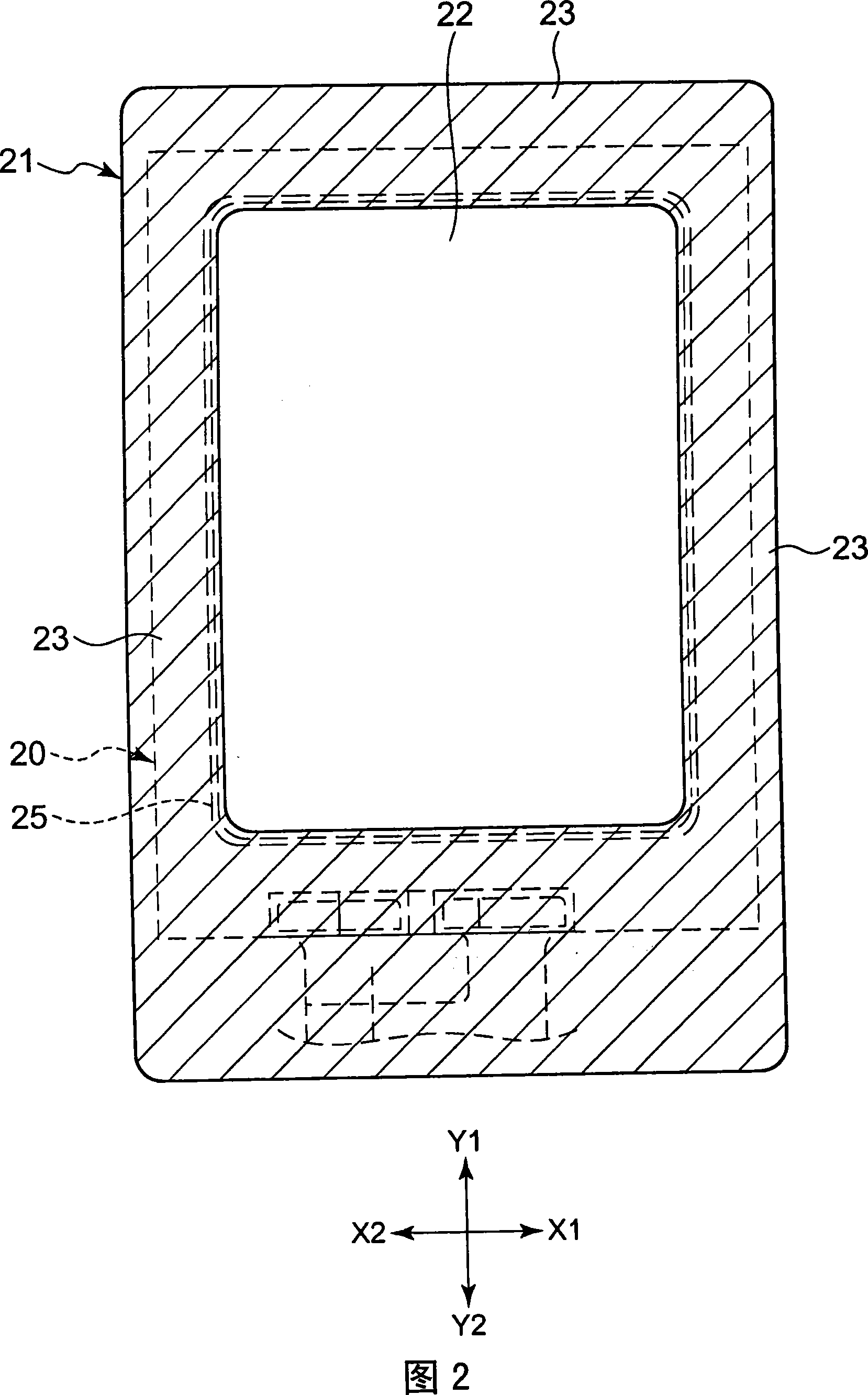
[0029] 1A is a cross-sectional view showing an electronic device equipped with a coordinate input device according to an embodiment of the present invention. FIG. 1B is an enlarged cross-sectional view showing a portion surrounded by ○ in FIG. 1A. FIG. 2 is a plan view showing a protective plate, and FIG. 3 is FIG. 4 is a plan view showing an upper panel constituting the coordinate input device, and FIG. 4 is a plan view illustrating a lower panel constituting the coordinate input device.

[0030] The electronic device 10 described below functions as a tablet (tablet) capable of inputting characters, graphics, etc., for example, to an internal coordinate input device. Alternatively, it functions as an electronic device having a switch function for receiving an input operation to the coordinate input device while viewing an image displayed on the display device installed on the lower stage. This type of electronic device 10 can be mounted on portable terminals such as mobile ph...


PUM


Abstract

To provide an electronic device that is difficult to see bubbles formed inside from the outside and has good visual confirmation. Grooves ( 39, 49). If the upper panel (30) and the lower panel (40) are bonded, the air bubbles (1) will be closed in the grooves (39, 49), since the grooves (39, 49) are formed in the non-permeable area as the non-visual recognition area. part (23), so it is difficult to see the air bubble (1) from the outside. Therefore, an electronic device with good visibility can be realized.

Description

technical field [0001] The present invention relates to electronic equipment capable of input operations, and more particularly to electronic equipment used with a display device. Background technique [0002] Conventionally, such electronic devices include, for example, a coordinate input device disclosed in Patent Document 1 below. [0003] In this coordinate input device, a resist layer having the same thickness as the X electrodes is filled without gaps in recesses formed between adjacent X electrodes (similar to the Y electrodes) on the substrate. Thus, the surface of the substrate having the electrodes is formed as a substantially flat surface with almost no unevenness, and the protective sheet is placed on the substantially flat surface and pressure-bonded to prevent air bubbles from forming between the substrate and the protective sheet. [0004] Patent Document 1: Japanese Unexamined Patent Publication No. 9-305289 [0005] In Patent Document 1, in order to preven...

Claims


Application Information

Patent Timeline
Patent Type & Authority Applications(China)
IPC IPC(8): G06F3/041H05K3/28
Inventor 大场克一桥田淳二
Owner ALPS ALPINE CO LTD
Learn More