

Substrate processing apparatus
A substrate processing device and substrate technology, applied to the original parts, transportation and packaging, cleaning methods and tools used for photomechanical processing, can solve the problem of difficult and efficient handling of multiple substrates, the increase in the number of substrate handling processes, and the central manipulator Complicated actions, etc.
- Summary
- Abstract
- Description
- Claims
- Application Information
AI Technical Summary
Problems solved by technology
Method used
Image

Examples
no. 1 approach
[0125] (1-1) Structure of substrate processing apparatus
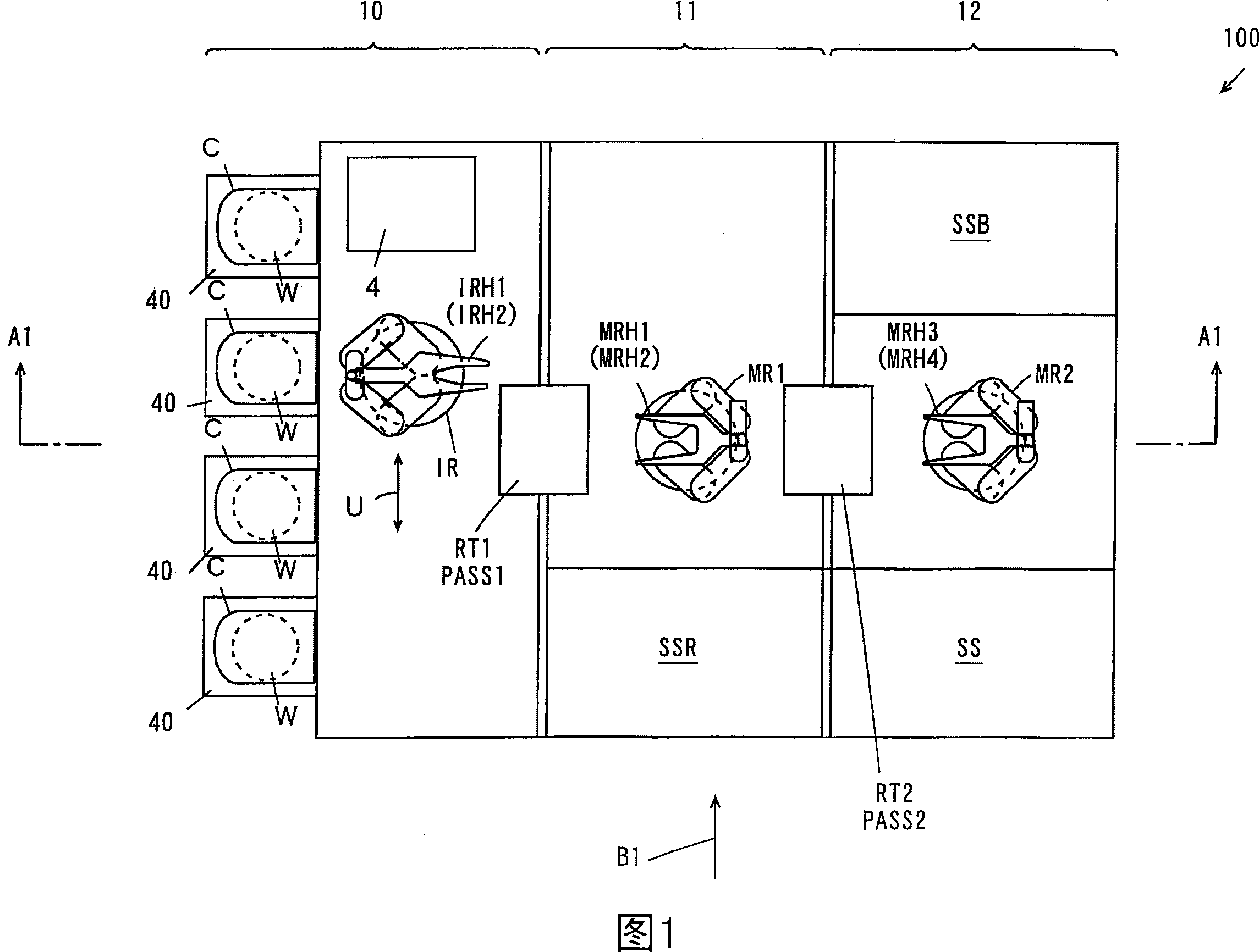
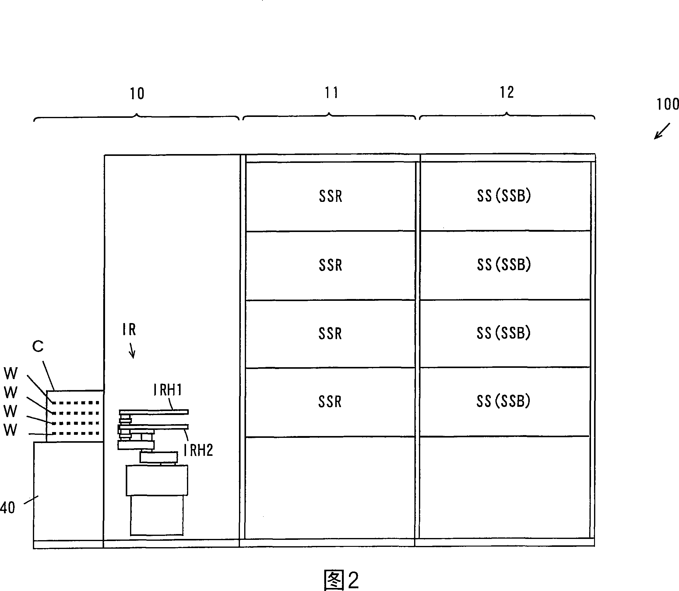
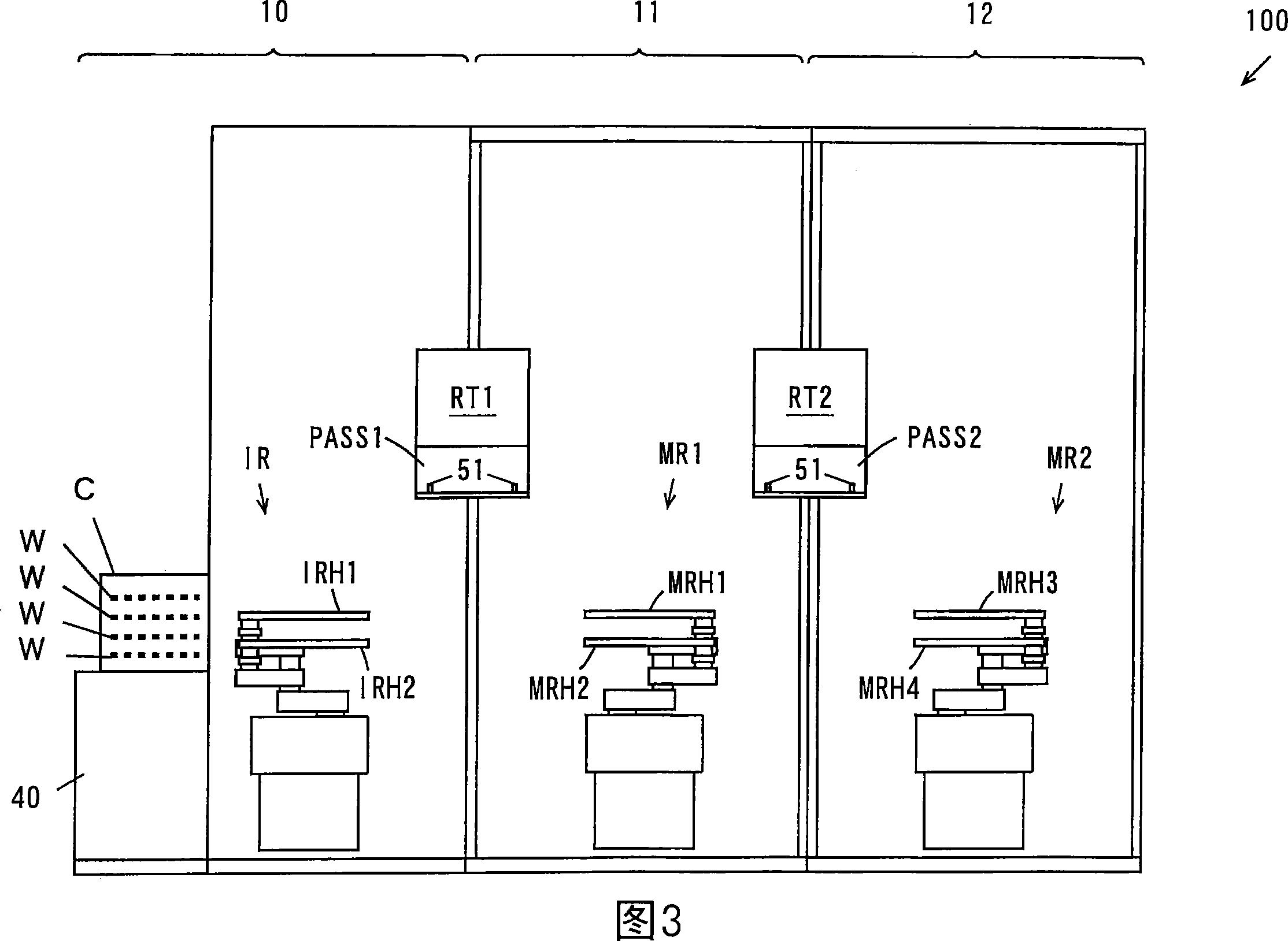
[0126] 1 to 3 are schematic diagrams showing the configuration of a substrate processing apparatus in the first embodiment. FIG. 1 is a plan view of a substrate processing apparatus, and FIG. 2 is a side view of the substrate processing apparatus in FIG. 1 viewed from the direction of arrow B1. In addition, FIG. 3 is a sectional view taken along line A1-A1 in FIG. 1 .
[0127] As shown in FIG. 1 , the substrate processing apparatus 100 is composed of an indexer block 10 , a first processing block 11 , and a second processing block 12 arranged side by side. In the indexer block 10, a plurality of carrier loading tables 40, an indexer robot IR, and a control unit 4 are provided. A carrier C for storing a plurality of substrates W in multiple layers is mounted on each carrier loading table 40 .
[0128] The indexer robot IR is configured to be movable in the arrow U direction, rotatable around a vertical axis, and mova...
no. 2 approach
[0212] Next, differences from the first embodiment described above will be described with respect to the substrate processing apparatus in the second embodiment of the present invention.
[0213] FIG. 12 is a schematic diagram showing the structure of a substrate processing apparatus in a second embodiment. As shown in FIG. 12, the substrate processing apparatus 100a in 2nd Embodiment is equipped with the following reversing units RT1a, RT2a instead of reversing units RT1, RT2. In addition, two substrate mounts PASS1 and PASS2 are respectively provided.
[0214] (2-1) Flip unit
[0215] FIG. 13A is a side view of the reversing units RT1a, RT2a, and FIG. 13B is a perspective view of the reversing units RT1a, RT2a. In addition, the reversing units RT1a, RT2a have the same structure.
[0216] As shown in Figure 13A, the turning unit RT1a, RT2a includes a support plate 31, a fixed plate 32, a pair of linear guide rails 33a and 33b, a pair of support members 35a and 35b, a pair ...
no. 3 approach
[0250] Next, differences from the first embodiment described above will be described with respect to the substrate processing apparatus in the third embodiment of the present invention.
[0251] (3-1) Structure of substrate processing apparatus
[0252] 16 and 17 are schematic diagrams showing the structure of a substrate processing apparatus in a third embodiment. FIG. 16 is a plan view of the substrate processing apparatus, and FIG. 17 is a sectional view taken along line A2-A2 of FIG. 16 .
[0253] As shown in FIG. 16 , in the substrate processing apparatus 100b of the third embodiment, a plurality of (for example, four) surface cleaning units SS are provided on one side of the first processing area 11 . In addition, a plurality of (for example, four) backside cleaning units SSR are arranged on one side of the second processing area 12, and a plurality (for example, four) of end surface cleaning units are arranged on the other side of the second processing area 12. Unit S...
PUM
 Abstract
Description
Claims
Application Information