Circuit for charging bootstrap capacitor of voltage converter

A technology of voltage converter and bootstrap capacitor, which is applied in the direction of output power conversion devices, instruments, electrical components, etc., to achieve the effect of improving system stability, small bandwidth and slow response speed

Active Publication Date: 2008-08-20
RICHTEK TECH
View PDF0 Cites 25 Cited by
  • Summary
  • Abstract
  • Description
  • Claims
  • Application Information

AI Technical Summary

Problems solved by technology

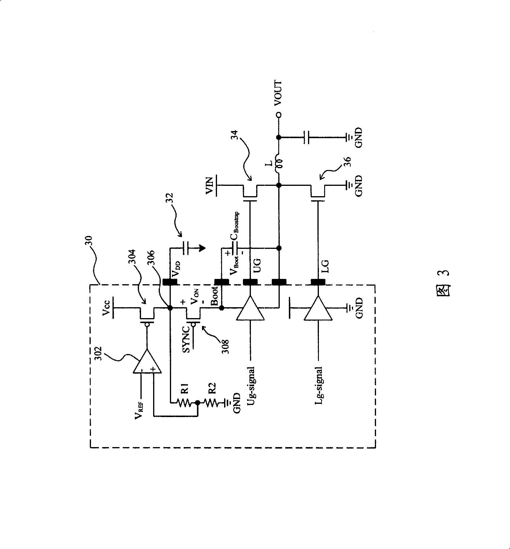
However, since the operational amplifier 302 needs to be compensated, a capacitor 32 must be ad

Method used


Image

  • Circuit for charging bootstrap capacitor of voltage converter
  • Circuit for charging bootstrap capacitor of voltage converter
  • Circuit for charging bootstrap capacitor of voltage converter

Examples


Embodiment Construction

[0028] Fig. 4 is an embodiment of the present invention, the transistor 406 is controlled by the synchronization signal SYNC, and is turned on or off synchronously with the lower bridge transistor 44, and the transistor 404 is connected to the power supply V CC between the transistor 406 and controlled by the signal CTL. In this embodiment, the transistors 404 and 406 use metal-oxide-semiconductor field-effect transistors (MOSFETs). In other embodiments, switch elements such as junction field-effect transistors (JFETs) can also be used. The node voltage between transistors 404 and 406 is V DD After being divided by the voltage dividing circuit composed of resistors R1 and R2, it is provided to the comparator 402 as the feedback voltage V FB , comparator 402 according to the feedback voltage V FB Is below the reference voltage V REF , generating a signal CTL to control the transistor 404 . If the feedback voltage V FB above the reference voltage V REF , the transistor 404...


PUM


Abstract

The present invention relates to a circuit for charging the bootstrap capacitor of the voltage converter, wherein, the voltage converter comprises a upper bridge transistor and a lower bridge transistor. The bootstrap capacitor is connected between the source of the upper bridge transistor and a driving electric source of the upper bridge driver. The circuit comprises a first transistor for connecting a power supply voltage and a feedback node, and a second transistor for connecting the feedback node and the bootstrap capacitor. The second transistor and the lower bridge transistor of the voltage converter are synchronously conducting and closing, a comparator obtains a feedback voltage from the feedback node and the first transistor is conducting when the feedback voltage is lower than a reference voltage, and the electric power voltage is provided to the second transistor thereby charging the bootstrap capacitor.

Description

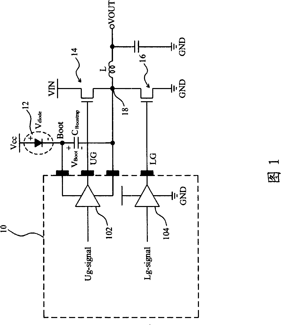
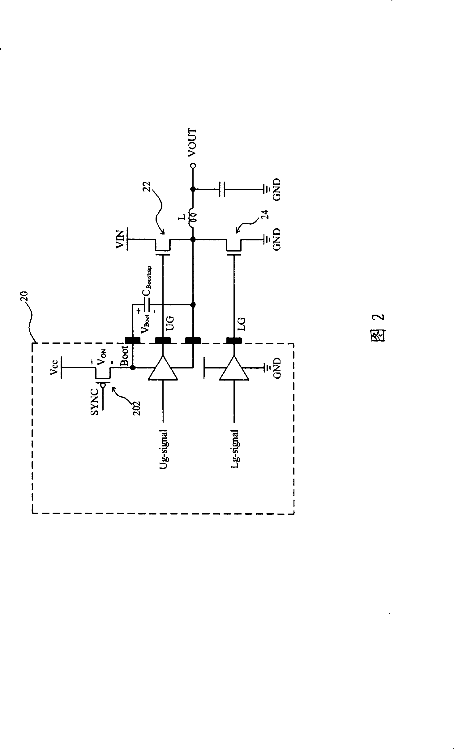
technical field [0001] The present invention relates to a voltage converter, and more particularly to a circuit for charging a boostrap capacitor of a voltage converter. Background technique [0002] 1 shows a part of the voltage converter. The upper bridge driver 102 and the lower bridge driver 104 in the controller chip 10 send the upper bridge drive signal UG and the lower bridge drive signal LG to the voltage according to the control signals Ug-signal and Lg-signal. The power stage of the converter switches the upper bridge transistor 14 and the lower bridge transistor 16 to convert the input voltage VIN into the output voltage VOUT. Assume that the power supply voltage V of the controller chip 10 CC is equal to the input voltage VIN, and the voltage converter in Figure 1 does not have diode 12 and bootstrap capacitor C Boostrap , then the voltage on the activation node Boot is the driving voltage provided to the high-bridge driver 102 and also the maximum gate voltage...

Claims


Application Information

Patent Timeline
IPC IPC(8): H02M3/155
Inventor 吕绍鸿陈曜洲
Owner RICHTEK TECH
Why Eureka
Try Eureka