Piezoelectric transducer, piezoelectric actuator, and portable device

A technology of piezoelectric vibration and piezoelectric elements, applied in piezoelectric devices/electrostrictive devices, electromechanical clocks, electric winding, etc., can solve the problems of enlarged amplitude, weakened amplitude, and inaccessibility

Inactive Publication Date: 2008-08-20
SEIKO EPSON CORP
View PDF5 Cites 12 Cited by
  • Summary
  • Abstract
  • Description
  • Claims
  • Application Information

AI Technical Summary

Problems solved by technology

[0019] In addition, in Patent Documents 1 and 4, the reinforcement plate and the piezoelectric element are not in contact at the belly of the bending vibration, but there is no reinforcement plate portion extending approximately in the longitudinal direction at the approximately central portion of the rectangular piezoelectric element in the width direction. (In Patent Document 1, this part is referred to as the arm part) The shape is considered in particular, and since the width of this part is very narrow, it may not be possible to use the reinforcement plate to limit the direction and attachment to the piezoelectric element.

Method used


Image

  • Piezoelectric transducer, piezoelectric actuator, and portable device
  • Piezoelectric transducer, piezoelectric actuator, and portable device
  • Piezoelectric transducer, piezoelectric actuator, and portable device

Examples


no. 1 approach

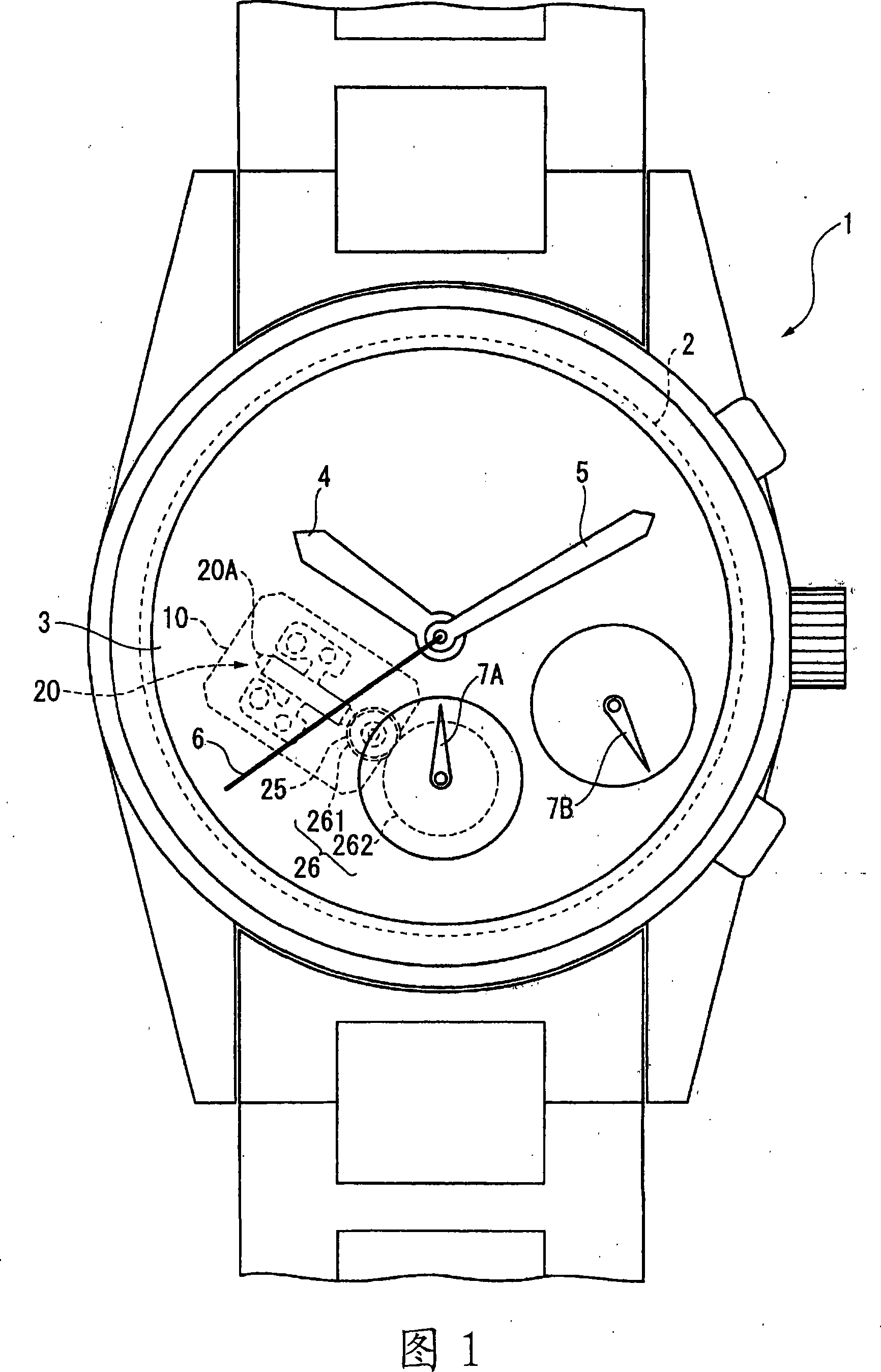
[0160] In this embodiment, a wristwatch equipped with a chronograph is shown as a portable device. In addition, in this embodiment, the structure which can expand the amplitude of a longitudinal vibration and can expand the amplitude of a bending vibration is shown.

[0161] [1. Overall structure]

[0162] FIG. 1 is a plan view showing a timepiece 1 according to the present embodiment. The watch 1 has: a movement 2; a dial 3 for displaying time; an hour hand 4; a minute hand 5;

[0163] The hour hand 4, the minute hand 5, and the second hand 6 are the same as those of a normal analog quartz watch. They are driven by the following components: a circuit board assembled with a crystal oscillator (crystal vibrator); a stepping motor having a coil, a stator, and a rotor; a drive train; and a battery.

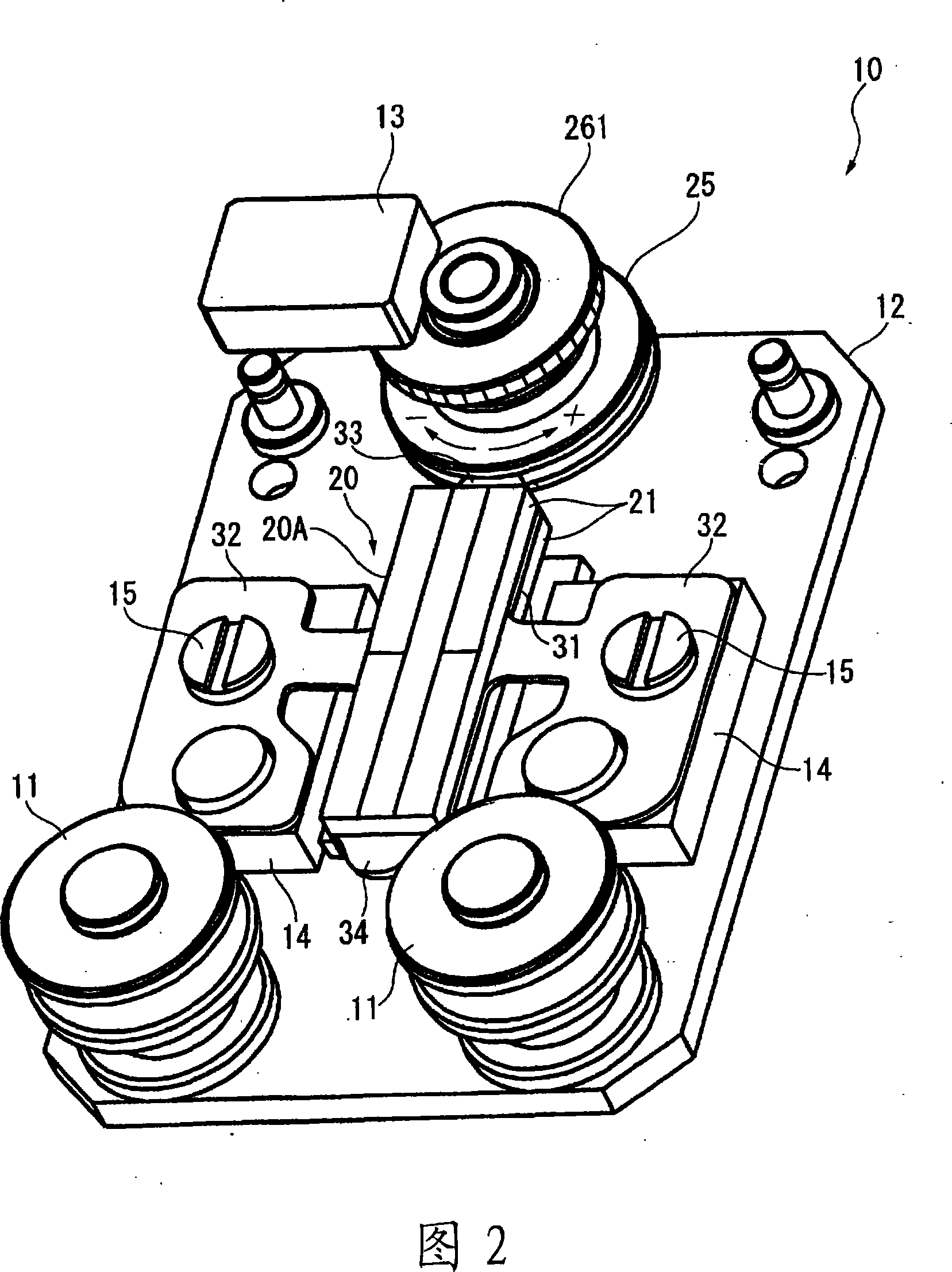
[0164] [2. The driving mechanism of the second hand of the chronograph]

[0165] The driving mechanism for driving the chronograph second hand 7A includes: a piezoelectric vibrat...

no. 2 approach

[0224] Next, a second embodiment of the present invention will be described. In this embodiment, the structure which can enlarge the amplitude of a longitudinal vibration and a bending vibration is shown.

[0225] FIG. 10 shows a piezoelectric vibrating body 40A of this embodiment. In this embodiment, only the shape of the reinforcing plate main body 41 laminated on the piezoelectric element 21 is different from the first embodiment, and the other structures are the same as those of the first embodiment.

[0226] The reinforcing plate main body 41 of this embodiment has substantially the same through hole 310 as that of the above-mentioned first embodiment, and has hollow holes 411 to 414 on both sides in the width direction of the reinforcing plate main body 41. These hollow holes 411 to 414 It is formed by hollowing out from the end edge of the reinforcing plate main body 41 corresponding to the outer edge portion 21A of the piezoelectric element 21 in the longitudinal direct...

no. 3 approach

[0238] Next, a third embodiment of the present invention will be described. In this embodiment, the structure which can enlarge the amplitude of a longitudinal vibration and a bending vibration is shown.

[0239] FIG. 12 shows a piezoelectric vibrating body 45A of this embodiment. In this embodiment, only the shape of the reinforcing plate main body 46 laminated on the piezoelectric element 21 is different from the above-mentioned respective embodiments, and the other configurations are the same as those of the above-mentioned respective embodiments.

[0240] The reinforcing plate main body 46 has: a central portion 461 that is laminated on the planar central portion of the piezoelectric element 21 and is formed with the through hole 310; Between the parts, extending through the central part 461; and a plurality of branch parts 463 formed to intersect the main line part 462, and the reinforcing plate main body 46 is formed in a shape similar to a fishbone.

[0241] Three bra...


PUM


Abstract

The present invention provides a piezoelectric vibrating body, a piezoelectric driver, and a portable device. The piezoelectric vibrating body can greatly expand the amplitude, thereby greatly improving the driving efficiency. According to the investigation of the vibration energy density in the piezoelectric vibrating body (40A), through-holes (310) and hollow holes (411-414) are formed in the reinforcement plate main body (41). The part with the greatest deformation caused by longitudinal vibration or bending vibration. In this way, at the through hole and hollow hole formed at the position containing the largest deformation due to longitudinal vibration or bending vibration, the maximum vibration energy in the piezoelectric element (21) is exerted to realize the expansion of the amplitude, and at the same time, by strengthening The displacement of the piezoelectric element (21) toward the out-of-plane direction is restricted by the parts other than the through hole (310) and hollow holes (411-414) in the plate main body (41), so the amplitude of longitudinal vibration and bending vibration is reliable. to expand.

Description

technical field [0001] The present invention relates to a piezoelectric vibrating body, a piezoelectric driver, and a portable device. Background technique [0002] Conventionally, in small and portable electronic devices such as watches, miniaturization and thinning of components to be mounted have been desired, and reduction in power consumption has been desired in order to prolong battery life. Therefore, instead of stepping motors, piezoelectric actuators that are small and thin and have excellent conversion efficiency from electrical energy to mechanical energy have been used as driving devices incorporated in timepieces (for example, Patent Documents 1 to 5). [0003] Such a piezoelectric actuator incorporated in a portable device, as shown in Patent Document 1, has a piezoelectric vibrating body having a generally rectangular plate shape in which a reinforcing plate is laminated on a rectangular piezoelectric element. The piezoelectric transverse effect when an elect...

Claims


Application Information

Patent Timeline
IPC IPC(8): H02N2/00H01L41/09G04C3/12
Inventor 山崎豊
Owner SEIKO EPSON CORP
Why Eureka
Try Eureka