
Method for designing trap parameter of magnetic suspension flat high speed rotor system

A high-speed rotor, wave trap technology, applied in the direction of holding devices, electrical components, etc. using magnetic attraction or thrust

Inactive Publication Date: 2008-08-20
BEIHANG UNIV
View PDF0 Cites 18 Cited by
  • Summary
  • Abstract
  • Description
  • Claims
  • Application Information

AI Technical Summary

Problems solved by technology

[0005] The technical problem of the present invention is: to overcome the defect that the existing method can only design the wave trap parameters of the weak gyroscopic effect magnetic suspension rotor system, and propose to adopt the dual-frequency Bode diagram to design the first-order elastic mode of the magnetic suspension flat high-speed rotor with strong gyroscopic effect The notch filter parameters for state self-excited vibration suppression solve the problem of notch filter parameter design for the strong gyro effect maglev elastic rotor system with the elastic modal stability margin as the goal, and ensure the stability of the elastic modal of the maglev high-speed rotor system and stability margin

Method used


Image

  • Method for designing trap parameter of magnetic suspension flat high speed rotor system
  • Method for designing trap parameter of magnetic suspension flat high speed rotor system
  • Method for designing trap parameter of magnetic suspension flat high speed rotor system

Examples


Embodiment Construction

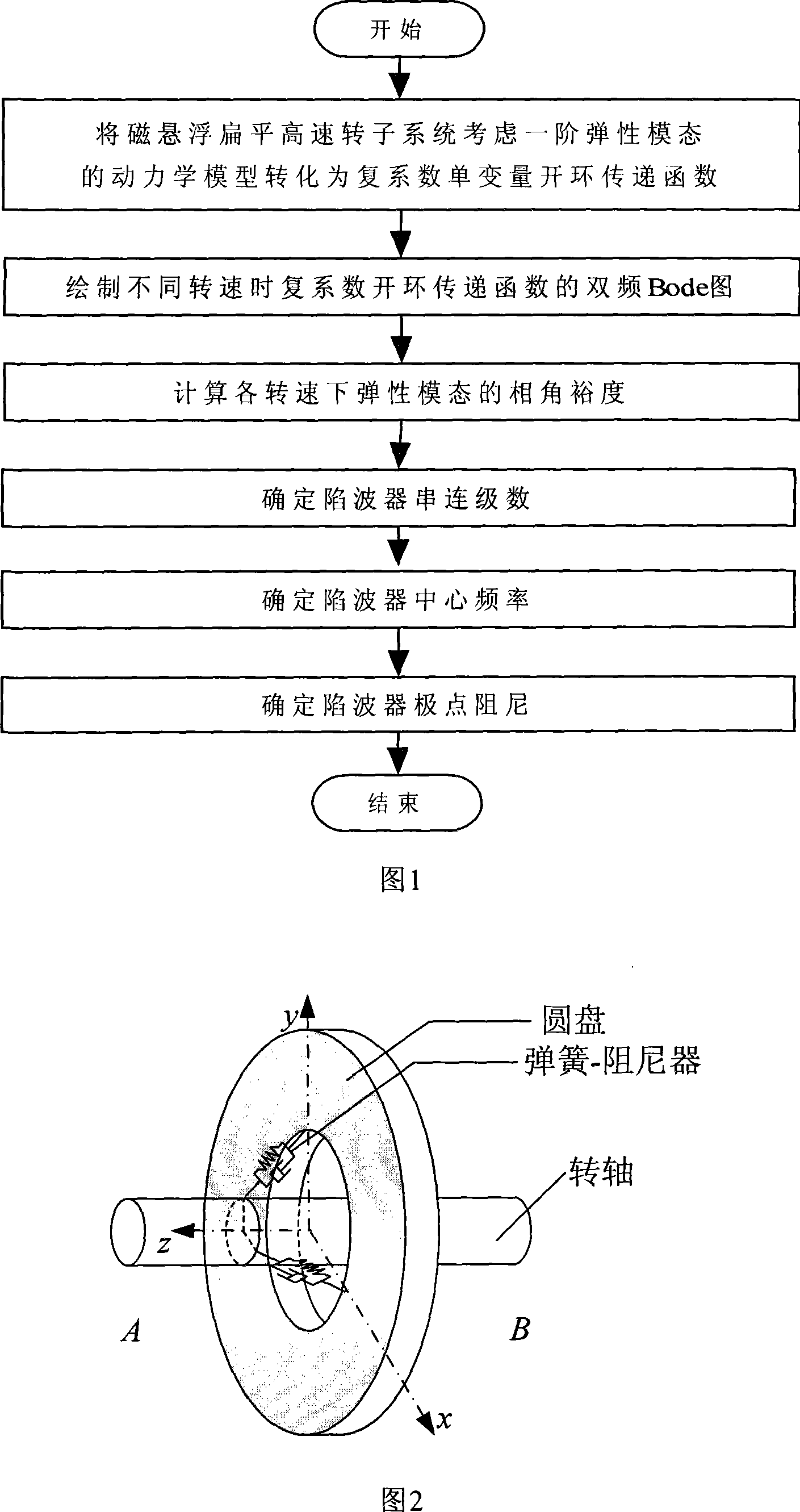
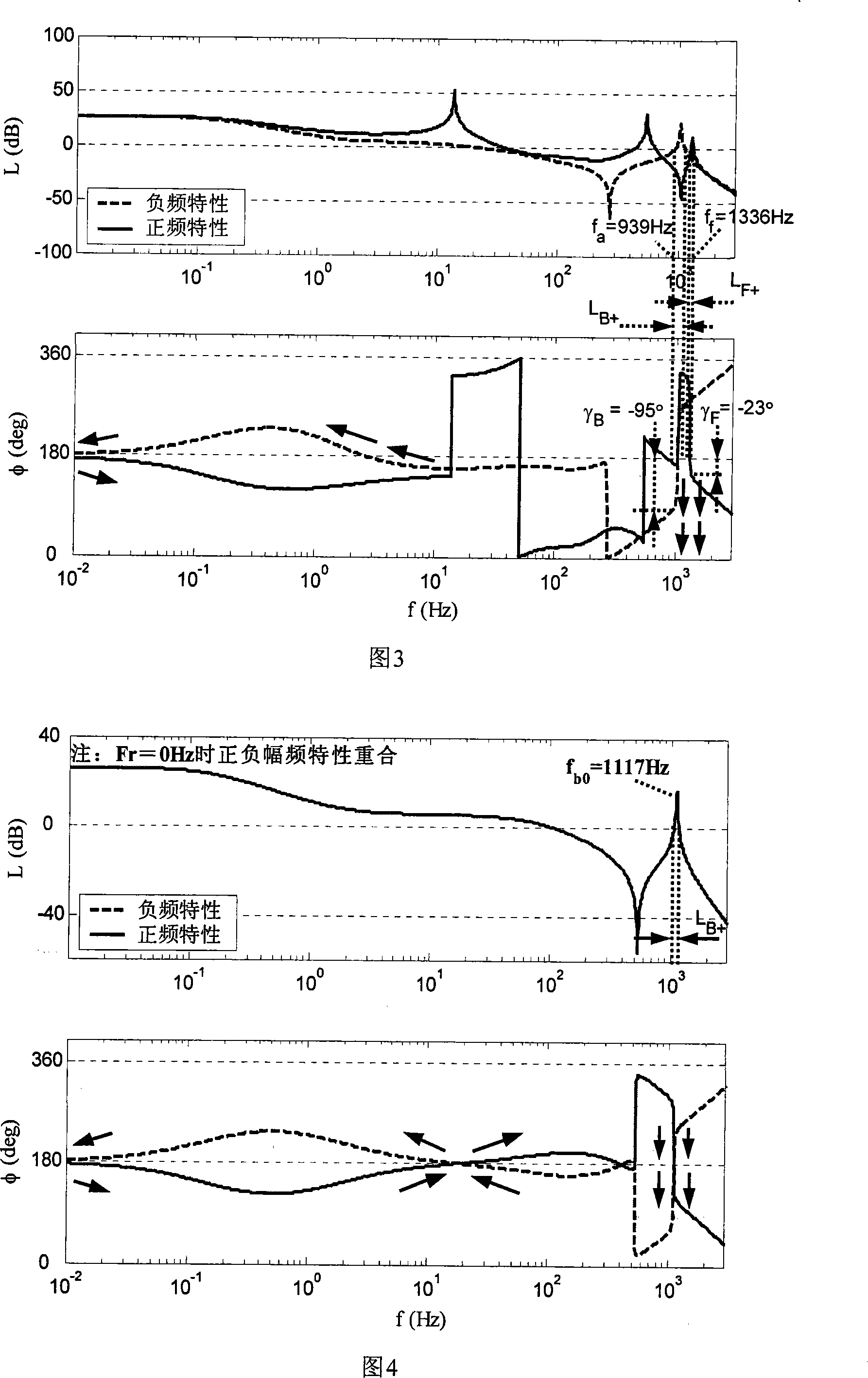
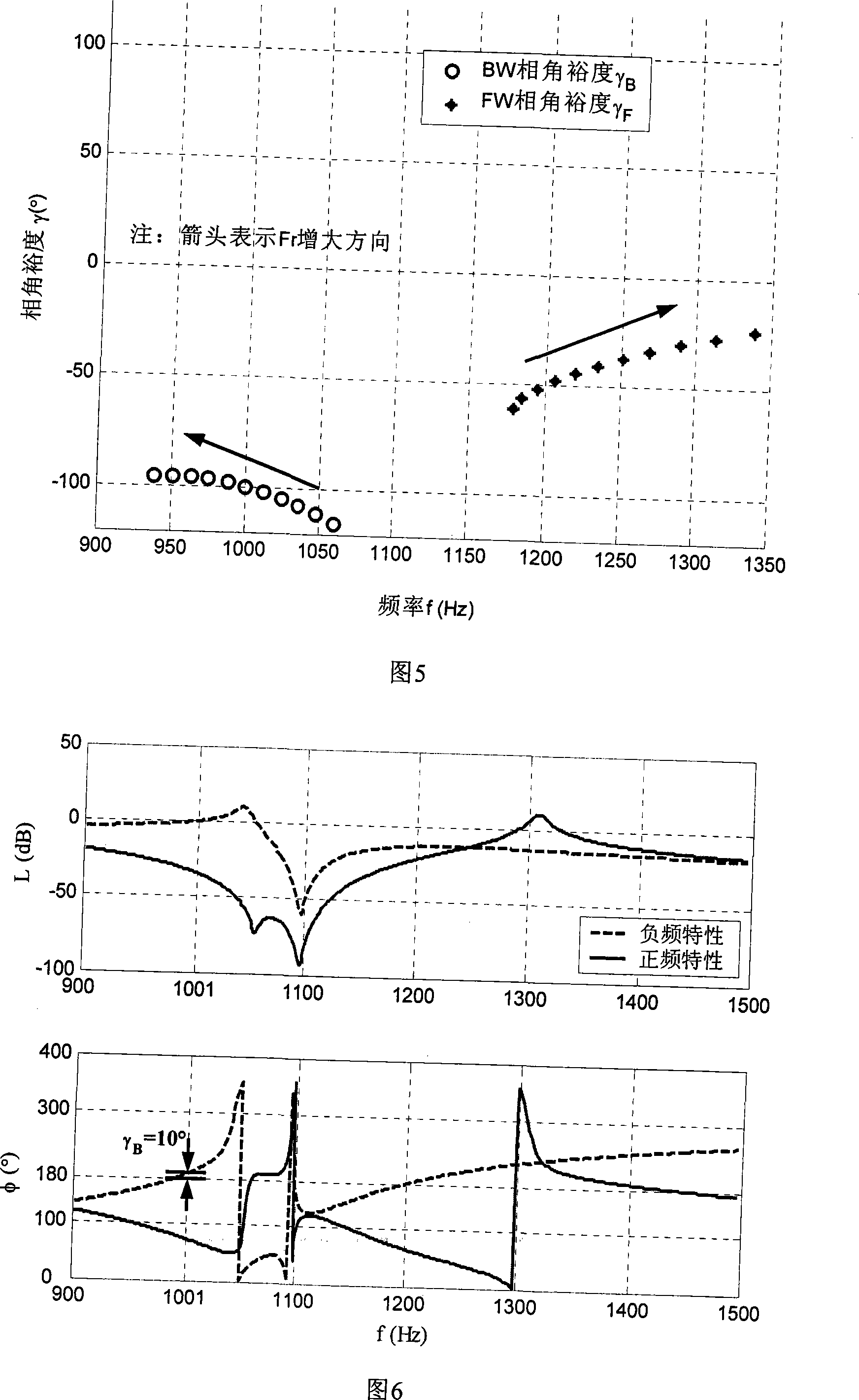
[0027] The invention discloses a method for designing wave trap parameters of a magnetically suspended flat high-speed rotor system. The specific implementation steps include: converting the dynamic model of the magnetically suspended flat high-speed rotor system considering the first-order elastic mode into a complex coefficient single-variable open-loop transfer function, and drawing The dual-frequency Bode diagram of the complex coefficient open-loop transfer function at different speeds, calculate the phase angle margin of the elastic mode at each speed, and design the series series, center frequency and pole of the suppression trap according to the phase angle margin curve Damping, as shown in Figure 1.

[0028] Taking a magnetically suspended flat elastic rotor system as an example to illustrate the specific implementation of the method of the present invention, the design target is the rotor speed F r=The phase angle margin of the next elastic mode at 0~400Hz is not les...


PUM


Abstract

The present invention provides a method for designing the parameter of the wave trap of the magnetic suspension flat high-speed rotor system. The magnetic suspension flat high-speed rotor system is considered with a kinetics model of the first order elastic mode and is translated into a complex-coefficient single-variate open-loop transfer function. The double-frequency Bode chart of the open-loop transfer function of the complex coefficient in different rotary speed is drawn. The phase angle allowance of elastic mode in each rotary speed is calculated, and the series-connected progression, central frequency and polar point amortization of the elastic self-excited vibration restraining used wave trap are designed according to the phase angle allowance curve. Basing on the double-frequency Bode chart the invention presents a method for designing the parameter of the wave trap which comprises a magnetic suspension flat high-speed rotor system with strong gyroscopic effect and is used for restraining the first order elastic self-excited vibration. Compared with the common multiple-variate system designing method such as state space analyzing method and the like, not only has excellent immediacy and robustness, but also can minimize the effect of the wave trap to the nutation stability, and thus the invention the invention is more suitable to be used in the actual magnetic suspension high-speed rotor system such as posture-controlling energy-accumulating fly wheel, the magnetic suspension counteracting wheel, the magnetic suspension control moment gyroscope and the like.

Description

technical field [0001] The invention relates to a wave trap parameter design method, which can be used in the design of wave trap parameters for elastic self-excited vibration suppression of a magnetic levitation flat high-speed rotor system with strong gyro effect. Background technique [0002] Compared with traditional mechanical ball bearings, magnetic bearings have outstanding advantages such as non-contact, active controllability of stiffness and damping, so there is no friction and wear, and no lubrication is required, allowing the rotor to rotate at high speed, with small vibration and high support accuracy, especially suitable for ultra- Clean environment equipment, high speed equipment and aerospace equipment requiring low vibration, high precision and long life. At present, the magnetic levitation high-speed rotor system has been increasingly widely used in civil and aerospace equipment such as centrifuges, high-precision CNC lathes, turbines, energy storage flywhe...

Claims


Application Information

Patent Timeline
IPC IPC(8): H02N15/00
Inventor 魏彤房建成樊亚洪王宗省韩邦成孙津济
Owner BEIHANG UNIV
Learn More