Power control method of passive optical network

A passive optical network and power control technology, applied in electrical components, electromagnetic wave transmission systems, transmission systems, etc., can solve the problems of optical power waste, ONU distances are far apart, and transmission power consumption is very large, so as to reduce power loss Effect

Active Publication Date: 2008-08-20
ZTE CORP
View PDF0 Cites 32 Cited by
  • Summary
  • Abstract
  • Description
  • Claims
  • Application Information

AI Technical Summary

Problems solved by technology

In the existing passive optical network, in order to enable all the expected ONUs to receive data stably, the optical splitter used is required to meet the requirement that among all the ONUs expected to be connected to the OLT PON port, the distance from the OLT PON port is the farthest The transmission power required by the ONU transmission to send optical signals, and the distance between multiple ONUs under the same optical splitter may vary greatly, which will cause a very large consumption of transmission power
In practical applications, since the activation status of the user may change, for example, a long-distance user has not activated the service, and the distance of the activated user is much smaller than this user, so the transmit power that satisfies the stable reception of data by the activated user will be far away. It is less than the transmission power that satisfies the long-distance user's stable reception of data, which will cause a waste of optical power, and the above-mentioned problems also exist for the uplink interface of the ONU

Method used


Image

  • Power control method of passive optical network

Examples


Embodiment Construction
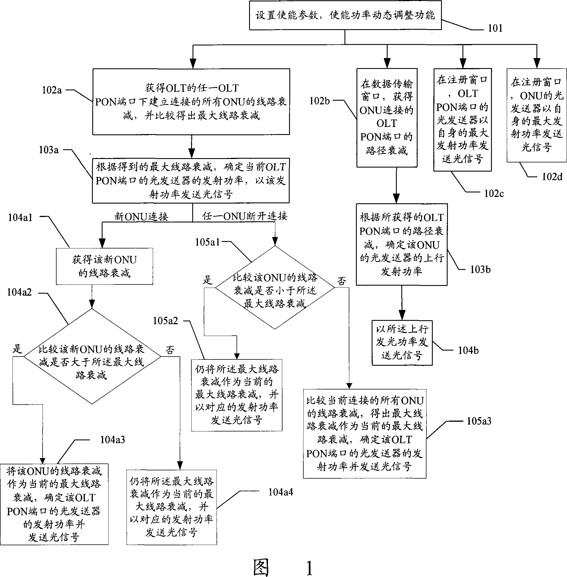
[0024] The basic idea of ​​the present invention is: in the registration window, the optical transmitter of the OLT PON port sends an optical signal with its own maximum transmission power, and the optical transmitter of the ONU sends an optical signal with its own maximum transmission power; in the data transmission window, dynamically adjust The transmit power of the optical transmitter at the OLT PON port enables all ONUs currently connected under the OLTPON port to receive the optical signals sent by the OLT PON port stably, which can reduce the power loss of the PON system; and, in the data transmission window , according to the path attenuation of the OLT PON port connected to the ONU, the maximum transmission power of the optical transmitter smaller than the ONU is obtained and used as the uplink transmission power, which can also reduce the power loss of the PON system.

[0025] The implementation process of the power control method in the passive optical network provid...


PUM


Abstract

The present invention discloses Power control method in passive optical network, light sender of OLTPON terminal port transmits light signal with self maximum emission power at register windows to assure all ONU register success successfully; all ONU with establishing connection below the OLTPON terminal port can steadily receives light signal transmitted from the OLTPON terminal port by dynamic adjusting emission power of light sender of OLTPON terminal port in data-transmission windows. Adopting method of the present invention can dynamic regulate light signal emission power of OLT and ONU in PON system, thereby power loss of PON system is decreased.

Description

technical field [0001] The invention relates to a power control technology in broadband access, in particular to a power control method in a passive optical network (PON, Passive Optical Network). Background technique [0002] With the continuous development of PON technology, PON technology provides users with higher access bandwidth, such as Gigabit Passive Optical Network (GPON, Gigabit Passive Optical Network) and Ethernet Passive Optical Network (EPON, Ethernet Passive Optical Network) The optical line terminal (OLT, Optical Line Terminal) of the central office equipment and the optical network unit (ONU, Optical Network Unit) of the terminal equipment are connected by optical fiber, and the optical splitter is used to realize the point-to-point The multi-point connection provides an access rate greater than 1Gbit / s, and the connection distance between the central office equipment and the terminal equipment can reach tens of kilometers, and the coverage area is wider. ...

Claims


Application Information

Patent Timeline
Patent Type & Authority Applications(China)
IPC IPC(8): H04B10/17H04B10/12H04B10/564
Inventor 袁立权
Owner ZTE CORP
Why Eureka
Try Eureka