High precision fiber filter

A fiber filter, high-precision technology

Inactive Publication Date: 2008-08-27
北京东方纪元水务工程有限公司 +2
View PDF3 Cites 3 Cited by
  • Summary
  • Abstract
  • Description
  • Claims
  • Application Information

AI Technical Summary

Problems solved by technology

[0005] The purpose of the present invention is to provide a mechanically compacted high-precision fiber filter, which solves the technical problem of unstable effluent quality,

Method used


Image

  • High precision fiber filter
  • High precision fiber filter
  • High precision fiber filter

Examples


Embodiment 1

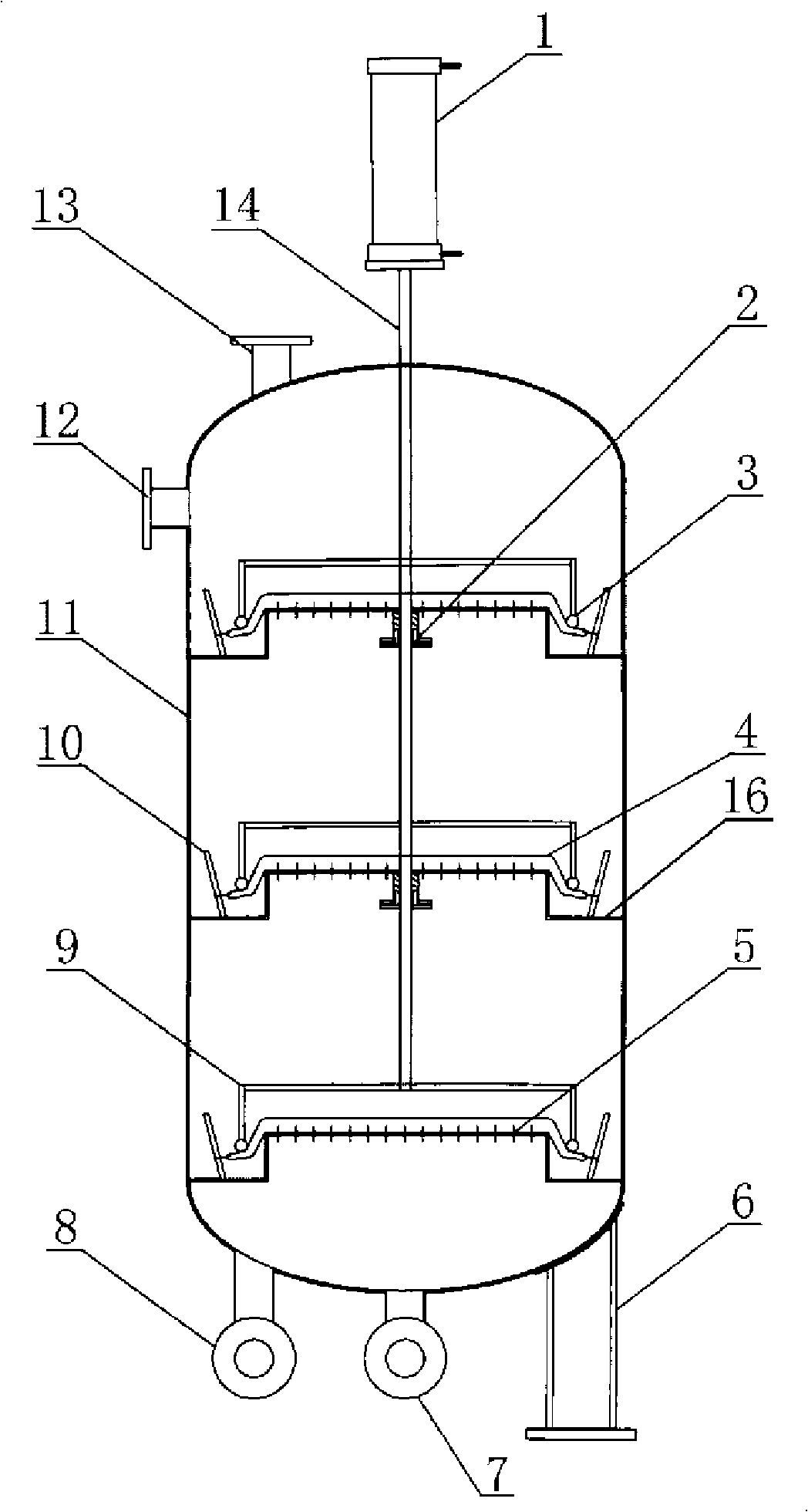
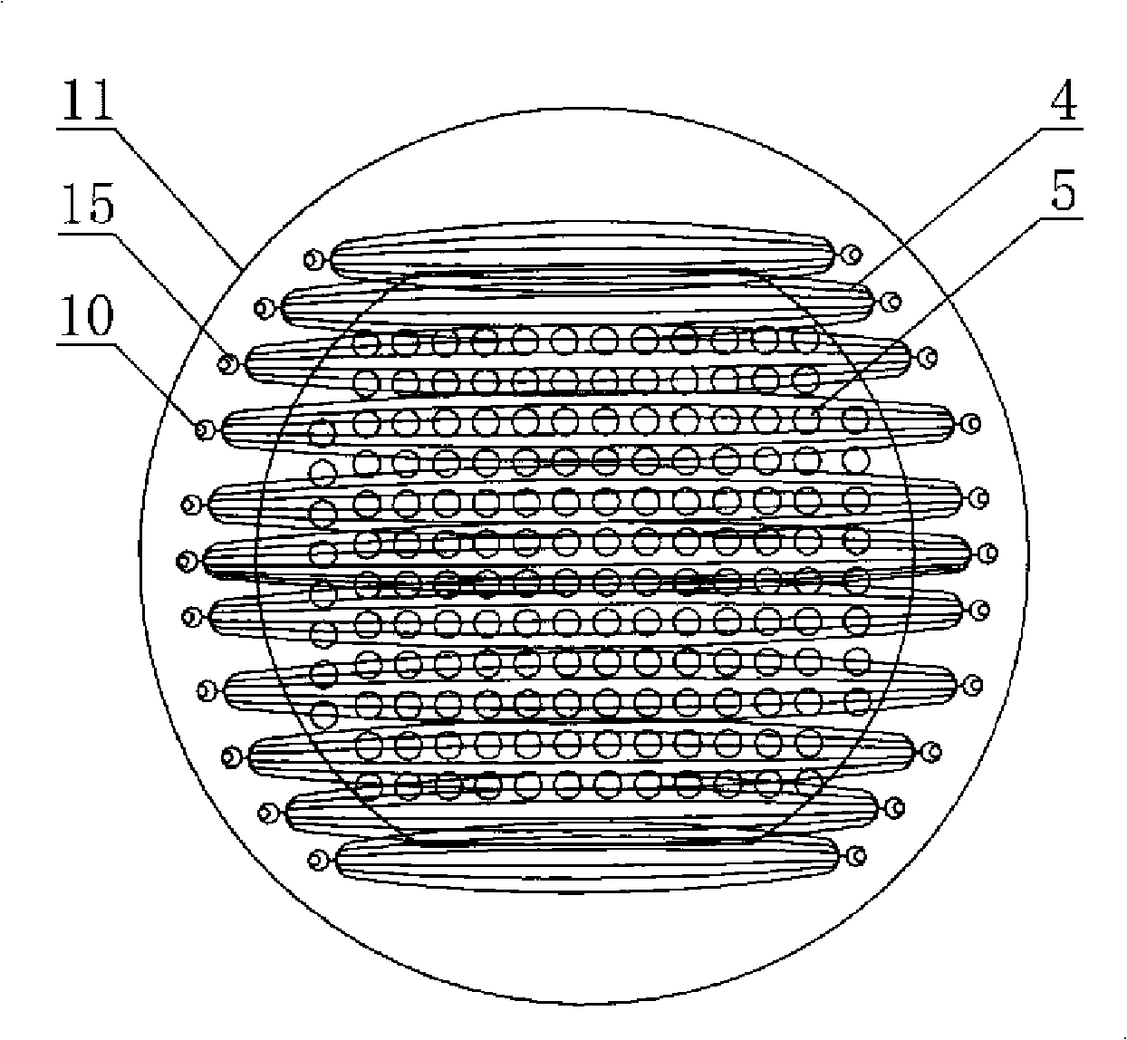
[0031] Embodiment one sees Figure 1-Figure 4 , this pot-shaped high-precision fiber filter includes a cylindrical housing 11, fiber bundles 4 inside the housing, and a hanging thread rod 10. There are water inlet pipes 12 and outlet pipes 7 on the housing. One end of the water outlet pipe is provided with a backwash air intake pipe 8, and one end of the water inlet pipe is provided with a backwash drain pipe 13. The inner wall of the housing is provided with at least one layer of L-shaped shelf ring 16 with an L-shaped cross-section. The horizontal plate of the L-shaped shelf ring is connected with the side wall of the housing. The vertical plate of the L-shaped shelf ring is covered with a perforated plate 5. The body or tank body is divided into one or more filter chambers, each filter chamber has one or more layers of fiber filaments, the fiber filaments are arranged in parallel to the porous plate, and hung on the hanging wire rod, and the fiber bundles are made of fiber ...

Embodiment 2

[0036] Embodiment two see Figure 5-Figure 8 , The difference from Embodiment 1 is that the casing of Embodiment 2 is a square tank with an open top, and the backwash drain pipe is located on the side of the casing. see Image 6 , the shape of the perforated plate is square, if it is used in open equipment, it does not need to be sealed.

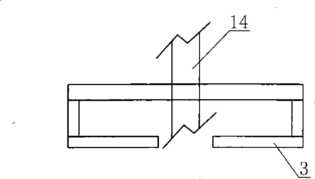
[0037] see Figure 7 , Figure 8 The above-mentioned fiber tensioning press frame 9 includes a frame connected to the drive shaft at the center and a depression bar under the frame, and the compression bar 3 is straight.

[0038] Working principle: When filtering, the driving device drives the fiber tensioning frame through the transmission shaft to press down the fiber bundle. The raw water passes through the multi-stage filter layer in the shell, and is filtered through the fiber layer step by step from top to bottom to become purified water. Discharged through the outlet.

[0039] During backwashing, the driving device drives the fib...


PUM


Abstract

A high-precision fiber filter includes a shell body, fiber beams in the shell body and a wire hanging rod, a water inlet pipe and a water outlet pipe are opened on the shell body, the inner wall of the shell body is provided with at least one layer of placing ring with an L-shaped cross-section, a transverse plate of the L-shaped placing ring is connected with the side wall of the shell body, porous plates are covered on a vertical plate of the L-shaped placing ring, at least one layer of fiber beam is covered on each layer of the porous plate, all the fiber beams are hung on the wire hanging rod which is arranged on the L-shaped placing ring, the upper surface of each layer of the fiber beam is pressed with a fiber tightening pressing frame with the diameter which is larger than the porous plate, all the fiber tightening pressing frames are connected with a transmission shaft at the center of the shell body, the transmission shaft penetrates out of the shell body to be connected with a drive device; the shell body is provided with a back wash air inlet pipe on one end of the water outlet pipe, and one end of the water inlet pipe is provided with a back wash water discharge pipe. The high-precision fiber filter has simple structure, low cost, easy back-wash, high filtration precision and small area coverage, which can greatly improve the water quality of the discharged water, solve the technical difficult problems of unstable water quality of the discharge water, accelerate the filtration speed and improve the effect of the solid-liquid separation.

Description

technical field [0001] The invention relates to a liquid-solid separation device, in particular to a fiber filter device. Background technique [0002] At present, the known fiber filter includes a housing, fiber bundles, fiber bundle supports, water inlet pipes, and water outlet pipes. It is a liquid-solid separation device with fiber bundles as the filter material. The compactness of the fiber bundles directly affects the quality and accuracy of filtration. . Chinese patent ZL92230672.9 discloses a fiber bundle filter, which adopts the arrangement of fiber filaments in a vertical porous plate, which causes the fiber filaments to be compressed into a filter layer in a disorderly manner, and the pores formed are relatively large, so that a thick bed is required to achieve Very good filtration accuracy. [0003] Chinese patent 00105869.X discloses a filter device that utilizes a capsule to compress the fiber layer. For example, the water flow direction is parallel to the fi...

Claims


Application Information

Patent Timeline
IPC IPC(8): B01D24/10B01D24/46
Inventor 沙中魁
Owner 北京东方纪元水务工程有限公司
Why Eureka
Try Eureka