
Gas compression method using end-face compression as well as end-face compression type electric drive gas source device

A gas source device and gas compression technology, which is applied to the components of pumping devices for elastic fluids, pump devices, liquid fuel engines, etc., can solve the problems of difficult manufacturing, high gas supply pressure, and unstable airflow, etc. Achieve enhanced adjustability and adaptability, increased pressure, and smooth airflow

Inactive Publication Date: 2008-08-27
张玘 +1
View PDF0 Cites 2 Cited by
  • Summary
  • Abstract
  • Description
  • Claims
  • Application Information

AI Technical Summary

Problems solved by technology

The compressed gas source device can provide the ventilator with gas suitable for pressure and flow requirements in places without power supply, but the steel cylinders storing compressed gas are heavy and not suitable for handling, so they are not suitable for field use. The capacity is limited, and it needs to be re-inflated after use, so it cannot be used continuously; the cylinder / airbag air source device has a large structural size, and the noise generated during operation is also relatively large, so it is not suitable for medical emergency situations, especially for sleep breathing machines etc.; the centrifugal fan air source device is difficult to achieve a higher air supply pressure, does not meet the air pressure requirements of emergency ventilators, and can only be used for sleep breathing machines; the turbine air source device is small in size and high in air supply pressure, but its structure is more complex, Manufacturing is difficult and costly; in addition, there are axial flow fans that can provide airflow, but the number of blades of axial flow fans is small, the airflow is not stable, and the air pressure that can be provided is small, so it is not suitable for ventilators

Method used


Image

  • Gas compression method using end-face compression as well as end-face compression type electric drive gas source device
  • Gas compression method using end-face compression as well as end-face compression type electric drive gas source device
  • Gas compression method using end-face compression as well as end-face compression type electric drive gas source device

Examples


Embodiment Construction

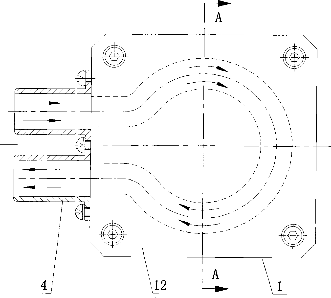
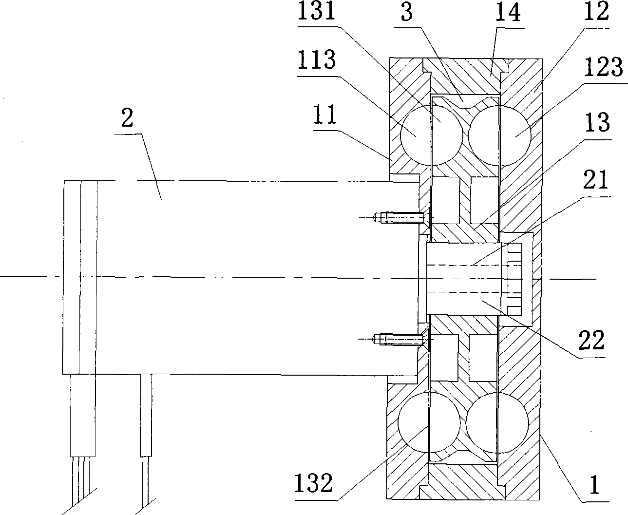
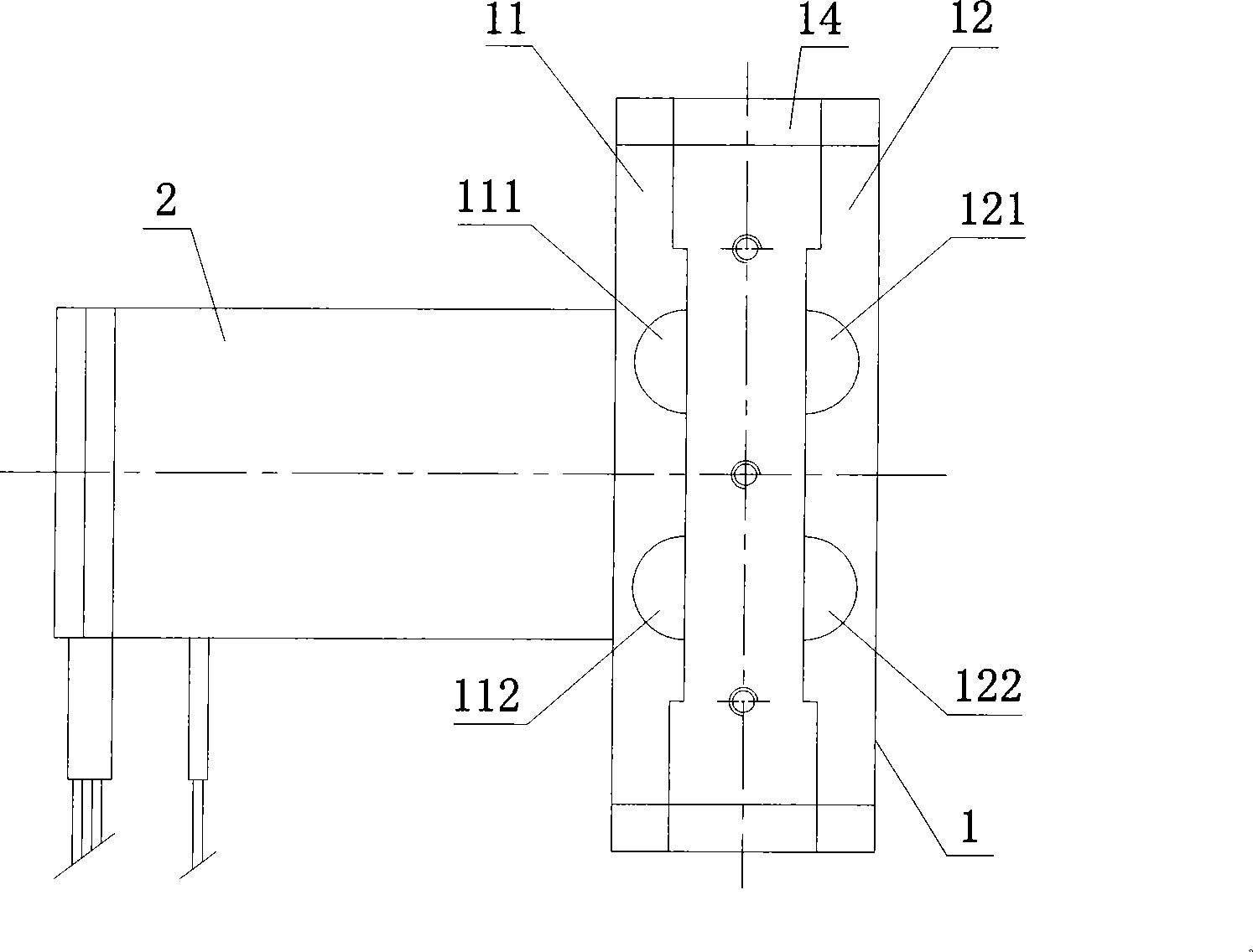
[0047] The gas compression method adopting end surface compression of the present invention, it is to arrange annular groove on both end surfaces of an impeller 13, arrange in the annular groove the blade 132 that evenly divides it into a plurality of compression units 131, this impeller 13 is installed on its In a matching closed cavity 3, air inlet ducts, air outlet ducts, and arc-shaped air guide slots corresponding to the position of the upper ring groove of the impeller 13 are arranged on both inner side walls of the closed cavity 3, and the arc-shaped air guide slots One end of the groove communicates with the air inlet channel, and the other end communicates with the air outlet channel. The motor drives the impeller 13 to rotate at a high speed, so that the gas enters the arc-shaped air guide groove from the air inlet channel, and the gas at both ends of the impeller 13 is compressed by the compression unit 131 Perform multi-stage compression, and then discharge the gas ...


PUM


Abstract

The invention relates to a gas compression method adopting end face compression and an end face compression electric air source device, wherein the method comprises the following steps: both end faces of an impeller are provided with ring grooves; the inside of each ring groove is provided with vanes which evenly divide the ring groove into a plurality of compression units; the impeller is arranged inside a closed cavity which is matched with the impeller; both inside walls of the closed cavity are provided with air inlet ducts, air outlet ducts and cambered gas guiding grooves corresponding to the positions of the ring grooves arranged on the impeller; one end of each cambered gas guiding groove is communicated with each air inlet duct, while the other end is communicated with each air outlet duct; the impeller is driven to rotate at high speed through a motor, thereby ensuring that gas is fed into the cambered gas guiding grooves from the air inlet ducts; multistage compression of the gas positioned at both end faces of the impeller is completed by means of the compression units arranged on the impeller; finally, gas is discharged from the air outlet ducts. The device comprises a drive motor, a first end cap, a second end cap, an outer ring and an impeller, wherein both end faces of the impeller are provided with ring grooves which are provided with a plurality of compression units inside. The method can provide stable air flow with high pressure ratio and mass flow; meanwhile, the device has the advantage of convenient carrying.

Description

technical field [0001] The invention relates to compressed gas source technology, in particular to a gas compression method using end face compression and an end face compression type electric gas source device. Background technique [0002] In the military, medical and industrial fields, many equipment need to use air source. In the medical and health field, the typical application of air source is ventilator. Air sources for ventilators can generally be divided into the following categories: compressed gas, cylinders / airbags, centrifugal fans, turbines, and axial fans. Except for compressed gas source devices, other gas source devices have power requirements and require batteries or External power supply. The compressed gas source device can provide the ventilator with gas suitable for pressure and flow requirements in places without power supply, but the steel cylinders storing compressed gas are heavy and unsuitable for handling, so they are not suitable for field use....

Claims


Application Information

Patent Timeline
Patent Type & Authority Applications(China)
IPC IPC(8): F04D29/26F04D29/40F04D29/00F04D25/06
Inventor 张玘吴石林
Owner 张玘
Learn More