
Lamination type radiator for vehicle

A car radiator, laminated technology, applied in the direction of heat exchanger type, indirect heat exchanger, lighting and heating equipment, etc., can solve the leakage, the difference between the coolant flow and the car radiator flow requirements, affect the core Heat dissipation efficiency and other issues

Inactive Publication Date: 2008-08-27
李政
View PDF0 Cites 8 Cited by
  • Summary
  • Abstract
  • Description
  • Claims
  • Application Information

AI Technical Summary

Problems solved by technology

[0005] 2 For cores with more than two rows of cooling flat tubes, there must be a technological gap of about 4mm between the tube rows. The heat dissipation belts in these gaps have no direct heat source, which affects the heat dissipation efficiency of the core.
[0006] 3 The four corners of the radiator and its surrounding areas are the parts that bear the greatest stress, and part of the stress needs to be transmitted through the cooling pipes connected to the four corners, so the side pipes on both sides of the radiator often break, weld, leak, or the side pipes and the main piece Accidents such as open welding and leakage of brazed joints
[0009] 2. The passages in the lamination stack are narrow, and the allowable coolant flow is very different from the flow requirements of the car radiator;
[0010] 3 Due to the strict brazing and sealing requirements of the lamination group and the structural characteristics of the lamination parts, the length of the lamination parts is restricted, so it is difficult to apply heat dissipation to larger power engines

Method used


Image

  • Lamination type radiator for vehicle
  • Lamination type radiator for vehicle
  • Lamination type radiator for vehicle

Examples


Embodiment Construction

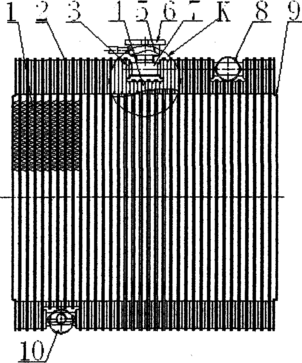
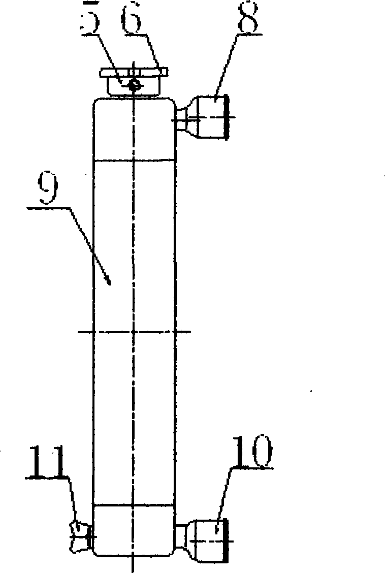
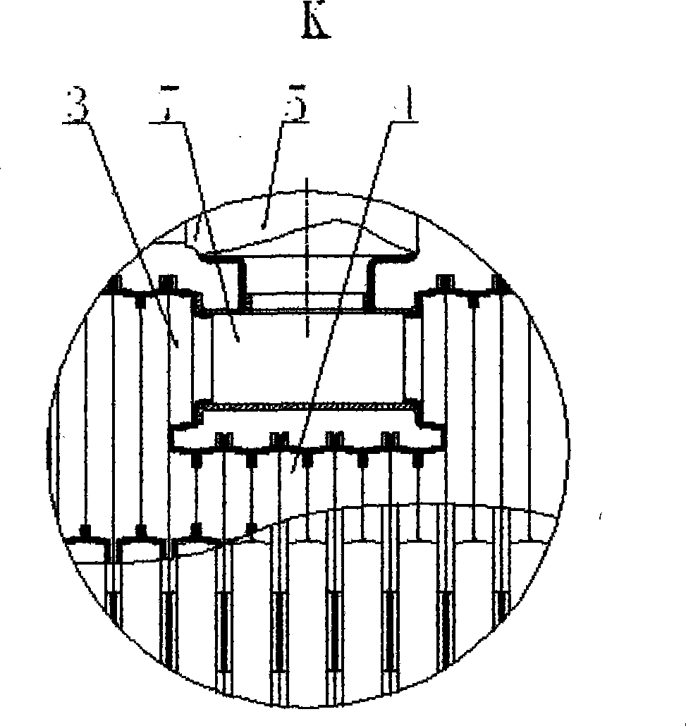
[0074] figure 1 It is the front view of the laminated car radiator according to the present invention. Ordinary laminations (2), small hole laminations (4), transitional laminations (3), heat dissipation strips (1), connecting pipes (7), water inlets (5), water inlet pipes (8), water outlet pipes (10 ), the side plate (9) is brazed in sequence, and the radiator cover (6) and figure 2 Drain valve (11) in.

[0075] Figure 4 It is the front view after the frame (13) is installed on the laminated car radiator according to the present invention, a rubber sheet (12) is added between the radiator and the frame (13), and it is fastened by a bolt assembly (14).

[0076] Figure 12 In the illustrated embodiment, a common lamination assembly is shown in Figure 10 The distribution and state of the inner rib bosses on the laminated parts after A-A is cut.

[0077] Figure 13 In the illustrated embodiment, a common lamination assembly is shown in Figure 10 After the B-B part of...


PUM


Abstract

A laminated membrane type automobile radiator is used for controlling working temperature of an automobile engine. A transition laminated membrane, a communicating pipe, a laminated membrane with small holes are arranged at the positions where a watering opening, an inlet branch, an outflow tube and a discharge valve seat are needed to be arranged, wherein the watering opening, the inlet branch, the outflow tube and the discharge valve seat are respectively welded on the communicating pipe. The laminated membrane parts are relatively and adhesively welded together to form laminated membrane components, one laminated membrane component is communicated with another laminated membrane component through braze welding external lug bosses of two ends of the laminated membranes, a heat dissipation strap is arranged between the laminated membrane components and connected through braze welding. The heat dissipation strap is changed into a flat bottom shape and connected with the laminated membrane plane, the width of the heat dissipation strap is less than the width of the laminated membrane part on the same core body, and the core body is changed into a concave strap shape. The laminated membrane type automobile radiator can also become laminated membrane type external type, oil cooling type, embedding type or assembling type automobile radiator, in order to widely meet the demands.

Description

technical field [0001] The invention relates to a key component in the cooling system of an automobile engine—radiator. Background technique [0002] The well-known automobile engine radiator has been born for more than 100 years. The mainstream structure of the radiator core has undergone a development from the tube fin type to the tube strip type, and then the aluminum material enters the radiator and expands with the copper radiator. In the situation of competing high and low, however, radiators have not made progress in breakthroughs in mainstream structures. [0003] Known automobile radiator is brazed and assembled by water chamber assembly, core body assembly and side plate assembly etc. Among them, most of the current core bodies are tube-belt structure. The wave-shaped heat dissipation belt and the cooling flat tube are placed at intervals and connected by brazing. Therefore, the radiator is also called a tube-belt radiator. This radiator has the following structu...

Claims


Application Information

Patent Timeline
IPC IPC(8): F28D1/053
Inventor 李政
Owner 李政
Learn More