Apparatus for calibrating gas instrument

An instrument verification and gas technology, which is applied in the field of equipment for the verification of gas flow detection instruments, can solve the problems of reduced vacuum pumping ability, environmental noise pollution, vacuum pump burnout, etc., and achieves the effect of reducing additional errors and avoiding noise pollution.

Active Publication Date: 2008-08-27
YUYAO YINHUAN FLOWMETER
View PDF0 Cites 13 Cited by
  • Summary
  • Abstract
  • Description
  • Claims
  • Application Information

AI Technical Summary

Problems solved by technology

The disadvantage is that when the gap between the required flow rate and the rated flow rate of the vacuum pump is large, the pipeline needs to be bypassed, otherwise the vacuum pump will also burn out
On the other hand, its pressure difference ratio is insufficient, and the highest foreign products can only reach 0.7 at present.
If the pressure loss of the verified instrument is slightly larger, the pressure difference ratio <0.85 at both ends of the sonic nozzle cannot be guaranteed, thus limiting the scope of use of the device
[0008] No matter which type of vacuum pump is used, the traditional gas meter verification device has one of the biggest and common defects: since the gas used for the verification is extracted from the outdoor atmosphere and discharged to the atmosphere, three problems arise. : One is that the temperature of the air extracted by the test cannot be controlled and is greatly affected by the outdoor temperature. Although it can be corrected by software, it brings additional errors in the correction calculation
The other is that because the air is discharged to the outdoor atmosphere, the noise is also taken out during the discharge, causing environmental noise pollution
Another one is that it is impossible to use frequency conversion technology
If the frequency conversion technology is used, for the gas ring vacuum pump, the decrease of the speed will make the pumping capacity of the pump drop rapidly, which cannot meet the verification requirements. For the water ring vacuum pump, when the speed drops, the average flow rate will be uniform The stability also deteriorates rapidly, which will bring uncertain factors to the test, which will cause errors in the test data and affect the authority of the test data.

Method used


Image

  • Apparatus for calibrating gas instrument
  • Apparatus for calibrating gas instrument

Examples


Embodiment Construction

[0027] The present invention will be further described in detail below in conjunction with the accompanying drawings and embodiments.

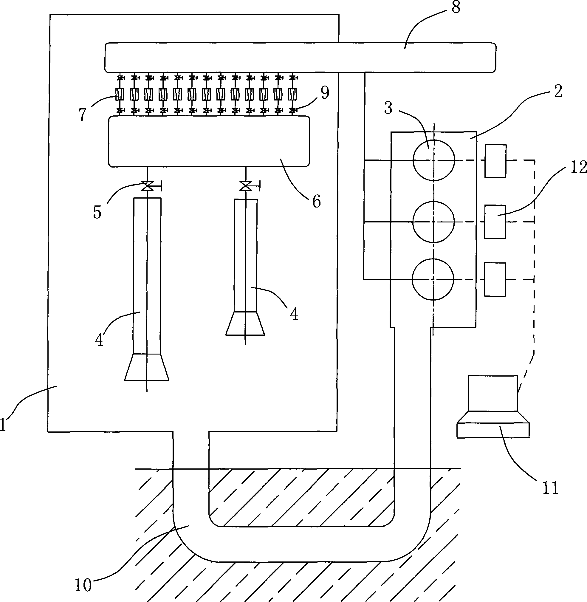
[0028] like figure 2 As shown, the gas instrument verification device of the present invention includes a sealable verification chamber 1 and a sealable soundproof chamber 2, and three Roots vacuum pumps 3 are arranged in the soundproof chamber 2, and two The verification station 4 where the flowmeter to be tested is placed, the verification station 4 is sequentially connected with a flow regulating valve 5, a stagnation container 6, a row of sonic nozzles 7, and a negative pressure pipeline 8. Both ends of the sonic nozzle 7 are equipped with There is an on-off valve 9, and the flow regulating valve 5, the stagnation container 6, the sonic nozzle 7, and the part of the negative pressure pipeline 8 corresponding to the sonic nozzle 7 are all arranged in the test chamber 1, and the negative pressure pipeline The rest of 8 protrudes out of the ...


PUM


Abstract

The invention discloses a gas instrument calibration device, which comprises a calibration platform for assembling a flowmeter to be tested. The calibration platform is at least connected with a stagnation container, a sonic nozzle, a negative pressure pipe and a Roots vacuum pump adopting the variable frequency control in turn. The calibration platform and the gas inlet of the calibration platform are arranged in a lockable calibration chamber, and the gas outlet of the vacuum pump is communicated with the calibration chamber through an underground duct. The gas instrument calibration device which has the advantages of low noise pollution, low energy consumption and small error is particularly suitable for the calibration of a gas flow measuring instrument.

Description

technical field [0001] The invention relates to verification or correction of flow meter equipment, in particular to a device for verifying gas flow detection meters. Background technique [0002] Standard meter method There are many methods for flow standard devices, and the gas flow standard device using the sonic Venturi nozzle (or sonic nozzle) as the standard meter is one of them. Compared with using other flowmeters as standard meters, using sonic nozzles as standard meters has many advantages, such as simple structure, stable performance, high accuracy, no moving parts, easy maintenance, long verification period (five years) and so on. The sonic nozzle method gas flow standard device is suitable for the detection and calibration of various gas flowmeters, and can detect mass flowmeters, velocity flowmeters, volumetric flowmeters, rotameters, differential pressure flowmeters or other types of flow count. [0003] The structure of the traditional sonic nozzle method g...

Claims


Application Information

Patent Timeline
Patent Type & Authority Applications(China)
IPC IPC(8): G01F25/00
Inventor 朱家顺
Owner YUYAO YINHUAN FLOWMETER
Why Eureka
Try Eureka