Concentric retaining sleeve of torsional specimen

A clamping sleeve and sample clamp technology, applied in the mechanical field, can solve the problems of difficult clamping of samples, affecting test accuracy, difficult operation, etc., and achieve the effect of improving test accuracy

Inactive Publication Date: 2008-08-27
XIAN TECHNOLOGICAL UNIV
View PDF0 Cites 7 Cited by
  • Summary
  • Abstract
  • Description
  • Claims
  • Application Information

AI Technical Summary

Problems solved by technology

[0004] 1) The two ends of the sample are easy to cause misalignment during the clamping process
2) The actual clamping length of the sample clamping section cannot be controlled, and it is easy to cause the pressing block to be pressed on the working section of the sample
3) At the end of the test, after the sample clamping section is taken out, the two briquetting blocks are easy to move along the briquetting block groove, blocking the sample inlet and making it

Method used


Image

  • Concentric retaining sleeve of torsional specimen
  • Concentric retaining sleeve of torsional specimen
  • Concentric retaining sleeve of torsional specimen

Examples


Embodiment 1

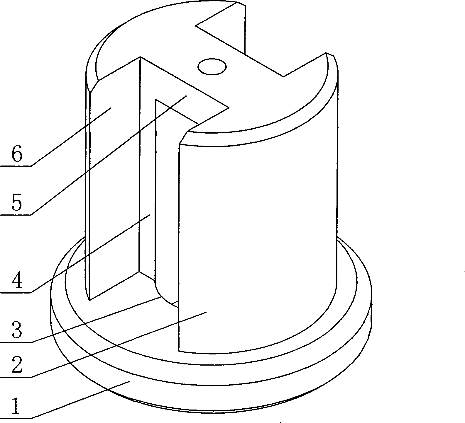
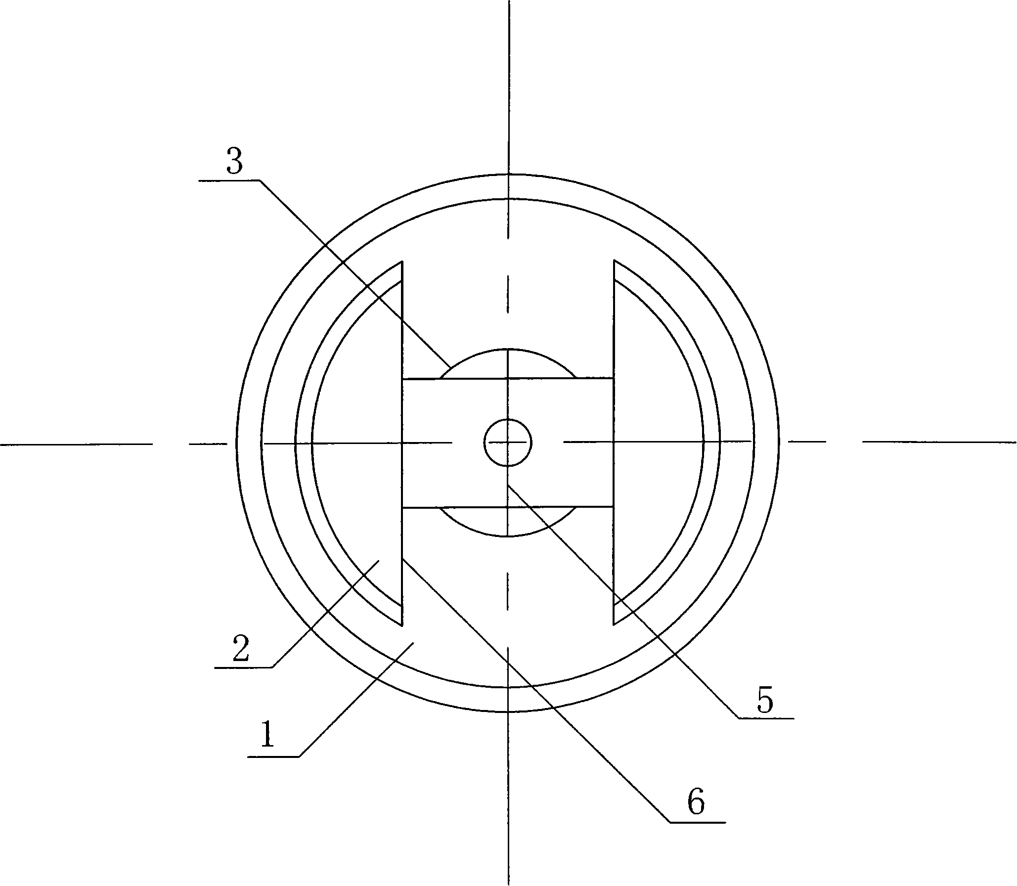
[0022] As a concentric clamping sleeve for torsion specimens, see figure 1 , including a base 1, a positioning wall 2, the outside of the positioning wall 2 is cylindrical, the positioning wall 2 is fixed on the base 1, the outer diameter of the positioning wall is smaller than the outer diameter of the base, and steps are formed on the edge of the base. The positioning wall 2 is two semicircular shapes whose end faces are connected together, and what connects the two end faces is the sample clamping section limiter 5 , and the plane of the base 1 is perpendicular to the positioning wall 2 . The processing of the positioning wall 2: one is to process the concentric positioning circular hole 3 on the original cylindrical body through the center of the base 1; . See also figure 2 , the arc-shaped inner wall in the middle section of the positioning wall 2 and the briquetting block limiting wall 4 are naturally formed by processing, which play the role of ensuring the concentr...

Embodiment 2

[0028] The overall structure is the same as that of Example 1. The limit stopper 5 of the sample clamping section connects the end faces of the two positioning walls 2 and is in the shape of a circular platform. It is formed by milling out two sealed rectangular grooves. At this time, the groove bottom of the rectangular groove is made of the square hole formed here by the concentric positioning circle 3 and the briquetting stop wall 4.

Embodiment 3

[0030] General structure is with embodiment 1,

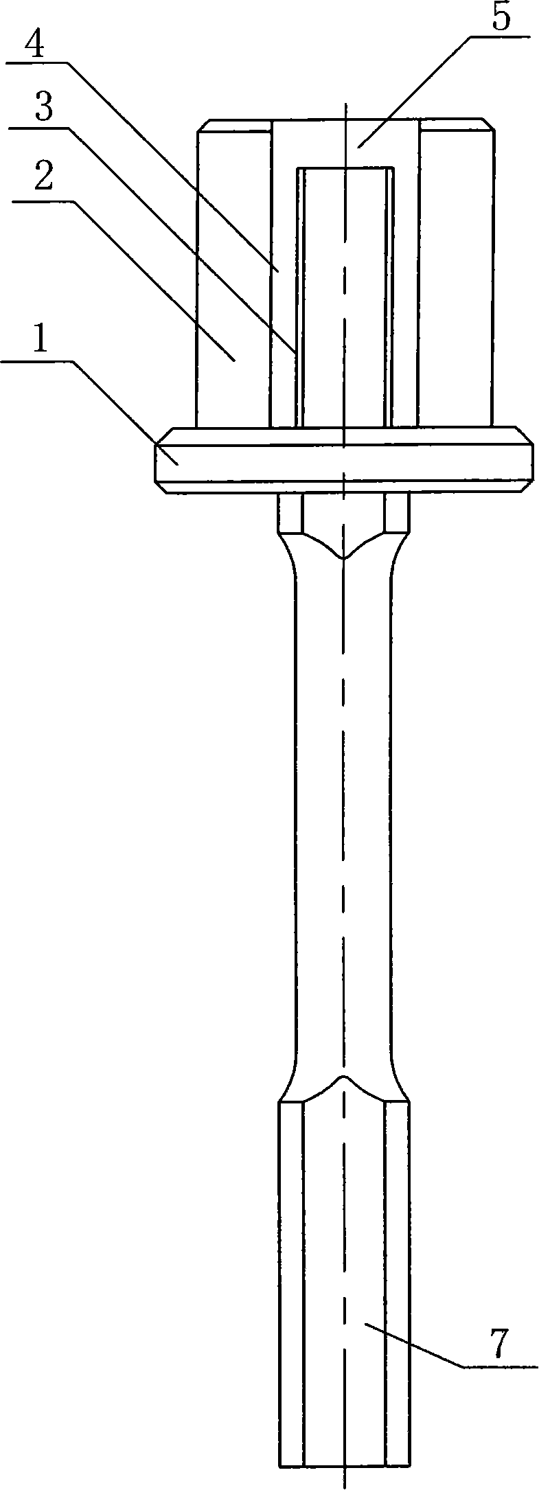
[0031] The concentric positioning circle 3, the diameter of its circular hole is based on the diameter of the sample clamping section 7, which is the dynamic fit tolerance, see image 3 . The outer circle of the positioning wall 2 corresponds to the size of the circular groove 10 on the chuck 9 of the torsion testing machine, which is a dynamic fit tolerance, see Figure 5 , after the clamping set is inserted into the chuck 9, the compression screw 12 is tightened so that the pressure block 8 is in accurate contact with the clamping surface of the sample, see Figure 4 , The sample clamping is accurate and firm, ensuring that the torsion sample is clamped reliably during the torsion process.


PUM

PropertyMeasurementUnit
Thicknessaaaaaaaaaa

Abstract

The invention relates to a torsion sample concentric clamping sleeve for fixing a sample in a torsional testing machine; in the design, a concentric setting circle 3 is added as the assurance of the concentricity of a sample clamping section; a limit crosspiece 5 of the sample clamping section is added as the pushing limit of the sample clamping section; a press block limit wall 4 is added as position limit to a press block, thereby ensuring that the sample is normally mounted and the press block is pressed on the fixed position of the clamping section. The invention solves the problems that the torsion sample is not concentric in the mounting and testing process, the position of the sample clamping section can not be determined and the sample is difficult in clamping, easy to skid and low in testing precision. The torsion sample concentric clamping sleeve provides the torsion sample concentric clamping sleeve with a stable integrated structure, light and simple, convenient and simple fixing and clamping, firm and reliable clamping and high testing precision, which can be widely used in material manufacturers of metal material, nonmetal material, machinery, building material, etc., the testing and authentication of new material research, material mechanics tests of technical authentication departments and universities and colleges and other occasions.

Description

technical field [0001] The invention belongs to the technical field of machinery, and mainly relates to a sample clamping device used in testing or testing equipment for testing material properties, in particular to a twisted sample concentric clamping sleeve used in a torsion testing machine. Background technique [0002] When testing the mechanical properties of a material or a new material, there is a routine test that is the torsion test. During the torsion test, due to the action of the torsion force on the sample, the sample is easy to slip during the torsion process, which affects the normal progress of the test process. , but also affect the accuracy of the test results. In order to eliminate this disadvantage, two planes are generally milled on the cylindrical clamping section of the sample for clamping, see image 3 . At the same time, some improvements have been made in the design and manufacture of the clamping device and the shape of the briquetting block of th...

Claims


Application Information

Patent Timeline
IPC IPC(8): G01N3/04G01N3/22
Inventor 许吉信
Owner XIAN TECHNOLOGICAL UNIV
Why Eureka
Try Eureka