Stack bus bar edge structure

An edge structure and laminated busbar technology, applied in the field of laminated busbars, can solve problems such as insulation failure, inability to ensure sealing, and potential safety hazards, and achieve reliable insulation and space-saving effects

Inactive Publication Date: 2008-08-27
SHANGHAI STEP ELECTRIC +1
View PDF0 Cites 11 Cited by
  • Summary
  • Abstract
  • Description
  • Claims
  • Application Information

AI Technical Summary

Problems solved by technology

However, bonding with adhesives cannot guarantee a complete seal. Once there is a gap and the extension length is

Method used


Image

  • Stack bus bar edge structure

Examples


Embodiment Construction

[0011] Below in conjunction with accompanying drawing and specific embodiment the present invention is described in further detail:

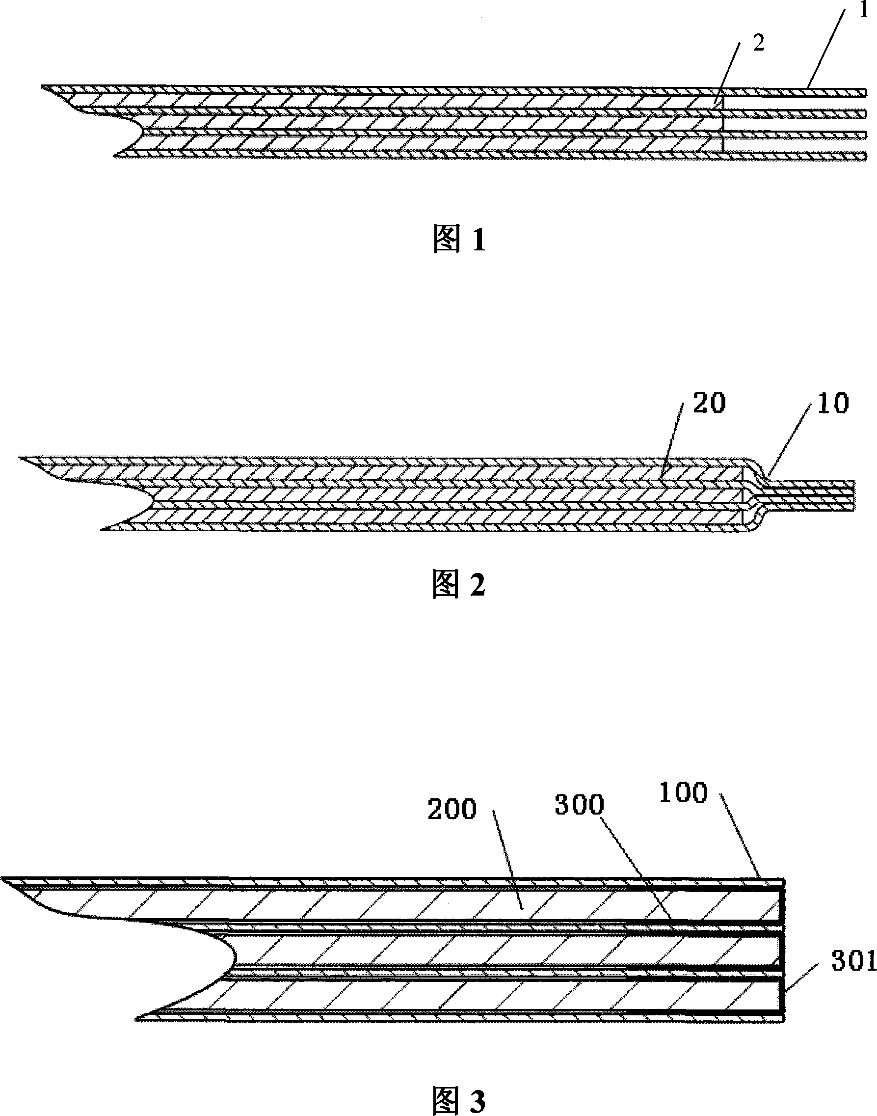
[0012] It can be seen from FIG. 3 that the present invention includes: at least one conductor layer 200 and an insulating layer 100 corresponding to the conductor layer 200; the insulating layer 100 is on both sides of the conductor layer 200; and the cladding layer 300 between the insulating layer 100; the cladding layer 300 is in adhesive contact with the conductor layer 200 and the insulating layer 100, and the end surface 301 of the cladding layer 300 is in contact with the conductor layer 200 and the insulating layer 100. flat edges;

[0013] The covering layer 300 is covered by insulating tape or coating.

[0014] In the prior art, the insulating layer needs to extend a certain distance from the conductor to ensure creepage. In the present invention, the edge of the conductor layer is inwardly covered with sufficient length of insulation...


PUM


Abstract

The invention relates to a marginal structure for a laminated busbar, comprising more than one layer of conductor layer(200) and an insulation layer(100) corresponding to the conductor layer(200), wherein the insulation layer(100) is arranged on both sides of the conductor layer(200); moreover, the invention also comprises a coating(300) inserted between the conductor layer(200) and the insulation layer(100), wherein the coating(300) is in sticking contact with the conductor layer(200) and the insulation layer(100) respectively, and has end surfaces(301) of the coating (300) paralleled with edges of the conductor layer(200) and the insulation layer(100); the marginal structure for a laminated busbar has the advantages of saving space due to the adoption of a mode of coating edges of conductors and further ensuring more reliable insulation.

Description

technical field [0001] The invention relates to a laminated busbar, in particular to an edge structure of the laminated busbar. Background technique [0002] At present, many electrical products begin to use laminated busbar technology to reduce parasitic inductance and obtain the best electrical performance. However, since the laminated busbar technology closely fits different conductors on both sides of the insulating layer, the distance between the conductors is very close, so the insulation between the conductors becomes a key factor in the design of the laminated busbar. [0003] For the insulation of the edge of the laminated busbar, there are two methods in the prior art: the first is to extend the edge of the insulating layer beyond the edge of the conductor layer, and the extension length is 1 / 2 of the maximum creepage distance between the conductors; the second is to Bond the extended insulating layer with an adhesive to seal it, and the extended length may be sho...

Claims


Application Information

Patent Timeline
IPC IPC(8): H02B1/20H01B5/02
CPCH02G5/005
Inventor 龚莉宋吉波高乾康守军孟庆旭
Owner SHANGHAI STEP ELECTRIC
Why Eureka
Try Eureka