Hot rolling facility of steel plate and hot rolling method

A steel plate and equipment technology, which is applied in the hot rolling equipment and hot rolling field of steel plate, can solve the problems of uneven temperature, damaged cooling water film, easily damaged cooling water film 53, etc., and achieve excellent equipment cost, good cooling capacity, Excellent equipment maintenance effect

Inactive Publication Date: 2008-08-27
JFE STEEL CORP
View PDF2 Cites 10 Cited by
  • Summary
  • Abstract
  • Description
  • Claims
  • Application Information

AI Technical Summary

Problems solved by technology

[0008] However, the technologies described in the above-mentioned Japanese Patent Application Publication No. 2002-361315 and Japanese Patent Application Publication No. 62-260022 have relatively large problems in terms of equipment cost, equipment maintenance, and cooling performance.
[0009] First, in the technology described in Japanese Patent Application Laid-Open No. 2002-361315, there is a problem that although the cooling water supplied to the upper surface of the steel plate temporarily stagnates on the steel plate, the cooling area of ​​the steel plate changes due to the change of the stagnant state, and thus High temperature control accuracy cannot be obtained
For example, as shown in FIG. 6 , when the discharge port of the slit nozzle 52 is clogged due to adhesion of a foreign substance 60 , the cooling water film 53 is destroyed.
In addition, in order to intercept the cooling water in the injection area (in the cooling area), it is necessary to spray at a high pressure, but when the film cooling water 53 is sprayed at a high pressure, the balance of the injection pressure becomes poor, and there is a problem that the cooling water film 53 is easily broken.
If the cooling water film 53 is not formed, the cooling water leaks to the upstream and downstream directions of the injection area, and it stays on the steel plate 10 to partially cool the steel plate 10, and there is a problem of uneven temperature.
There is also a technique to remove the cooling water remaining on the upper surface of the steel plate 10 with a side sprayer, etc., but it cannot be completely removed when the amount of cooling water is large, and there is still a problem of temperature deviation.

Method used


Image

  • Hot rolling facility of steel plate and hot rolling method
  • Hot rolling facility of steel plate and hot rolling method
  • Hot rolling facility of steel plate and hot rolling method

Examples


Embodiment 1

[0057] As Example 1 of the present invention, controlled rolling on a hot rolling line for thick steel plates was performed. Here, after the sheet thickness was rolled to 28 mm, controlled rolling at a predetermined rolling temperature was performed in the last three passes.

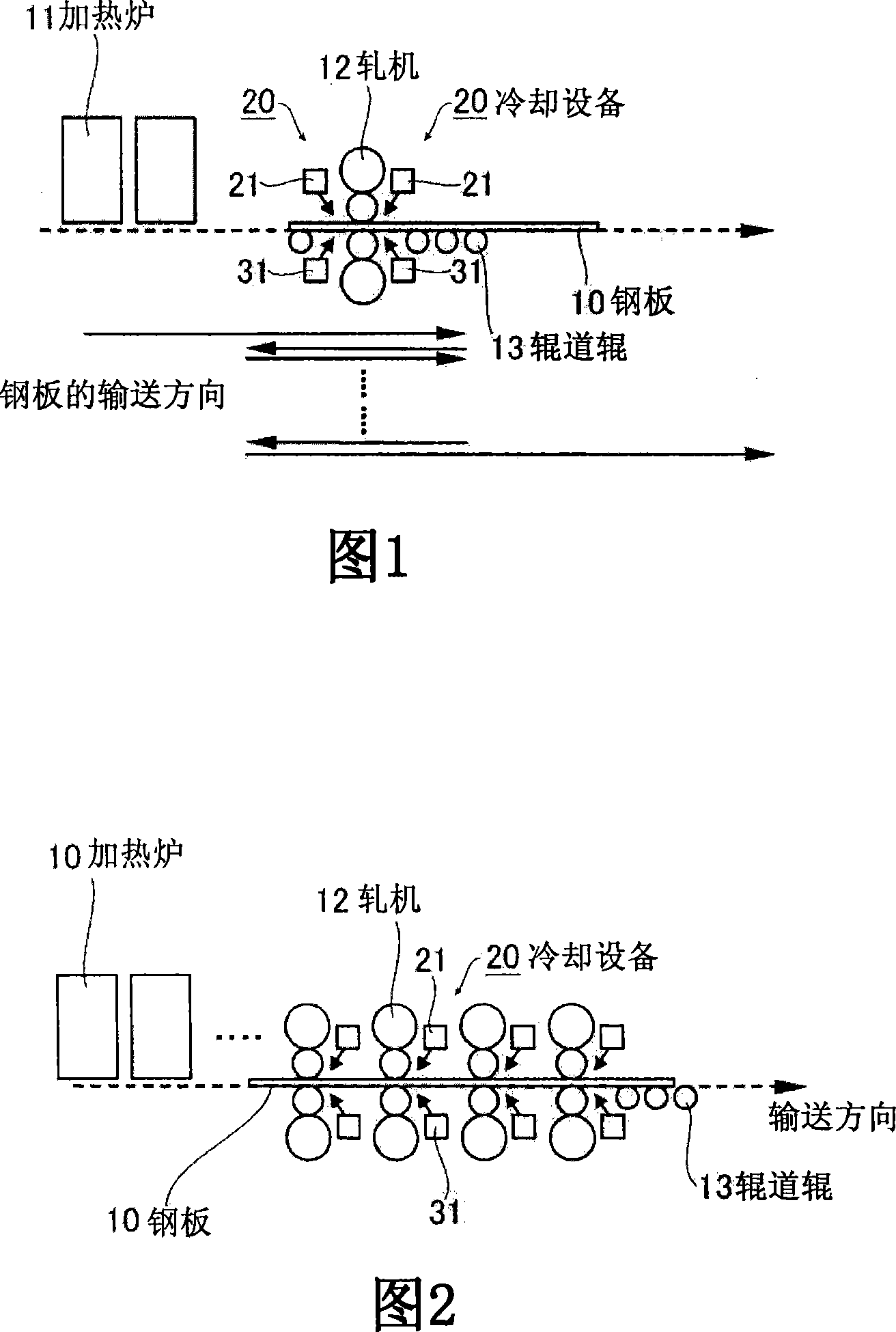
[0058] At this time, as Example 1 of the present invention, in the 4 passes before the controlled rolling using the hot rolling facility ( FIG. 1 ) shown in the above-mentioned embodiment, the cooling facility provided on the entrance side and the exit side of the rolling mill 12 20. Rod-shaped cooling water is sprayed to cool the steel plate 10 so that the temperature of the steel plate 10 at the end of the 4th pass is rolled to a predetermined temperature, and then controlled rolling is performed in the last 3 passes.

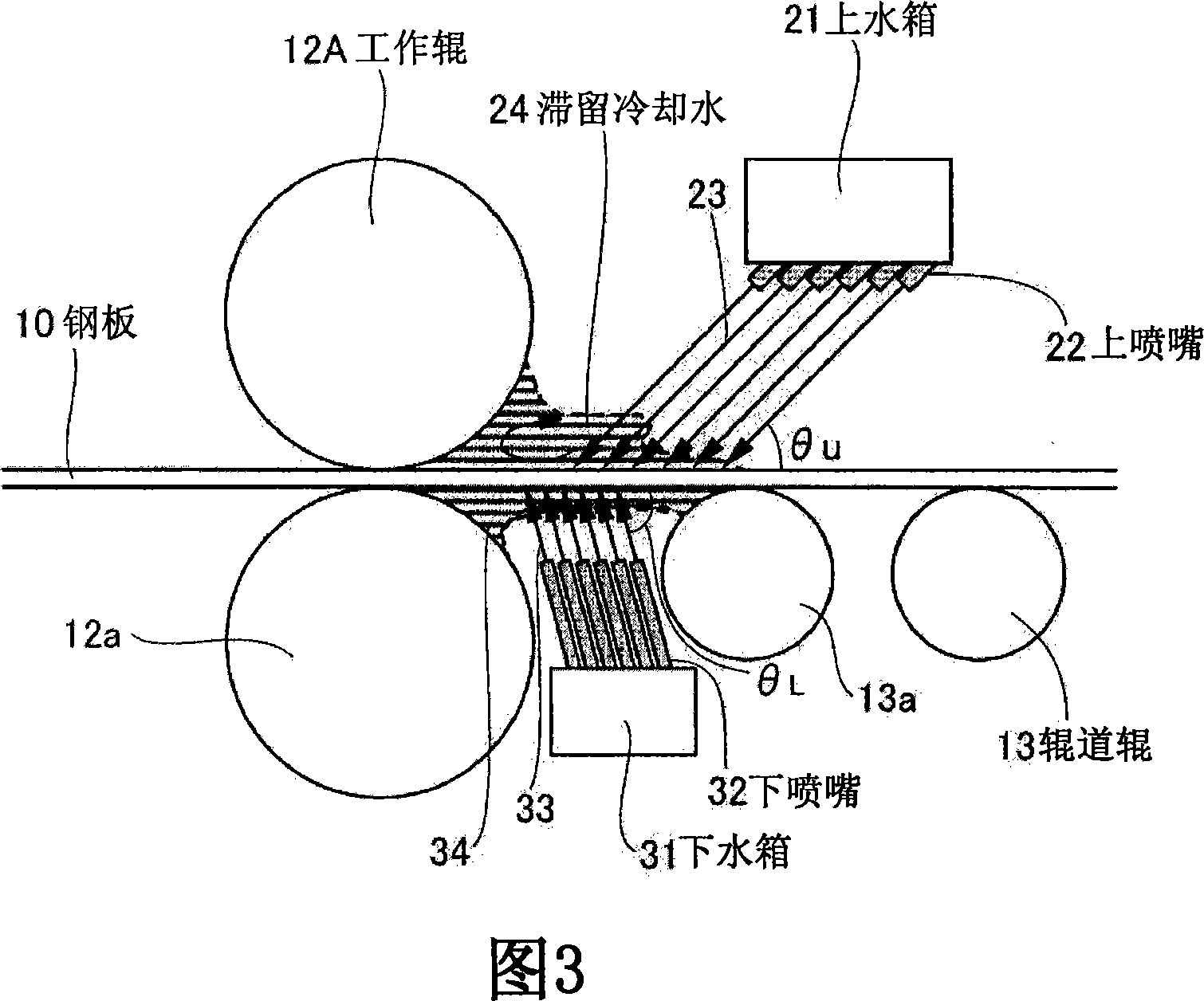
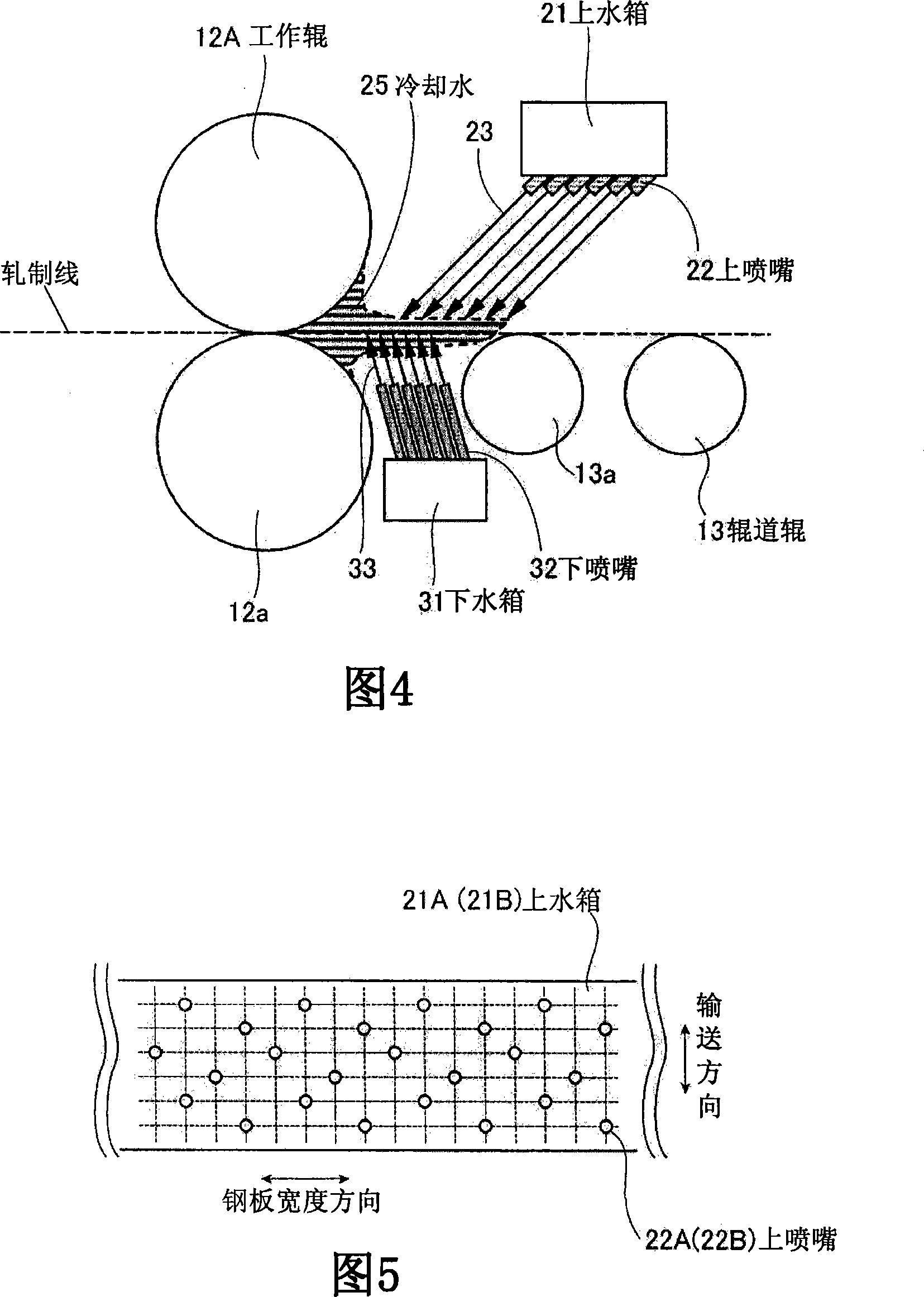
[0059] Among them, set the depression angle θ of the upper nozzle 22 U is 45°, the elevation angle θ of the lower nozzle 32 L for 60

[0060] In addition, the inner diameters of the ...

Embodiment 2

[0075] As Example 2 of the present invention, rough rolling on a hot rolling line for thin steel sheets was performed. Here, the steel slab was rolled to a plate thickness of 42 mm by a rough rolling mill.

[0076] At this time, as Example 2 of the present invention, using the hot rolling facility ( FIG. 1 ) shown in the above-mentioned embodiment, in the three passes of rough rolling, from the cooling facility 20 provided on the entrance side and the exit side of the rolling mill 12 Rolling is performed while cooling the steel plate 10 by spraying rod-shaped cooling water. Among them, set the depression angle θ of the upper nozzle 22 U is 45°, the elevation angle θ of the lower nozzle 32 L is 60°. In addition, the inner diameters of the upper nozzle 22 and the lower nozzle 32 were 6 mm, and the injection speed of the rod-shaped cooling water was 8 m / s.

[0077] On the other hand, as Comparative Example 3, rough rolling was performed using a hot rolling facility not equipp...

Embodiment 3

[0091] As Example 3 of the present invention, finish rolling on a hot rolling line for thin steel sheets was performed. Here, rolling was carried out by the 7-stand finishing mill of F1 to F7 to a final plate thickness of 3 mm.

[0092] At this time, as Example 3 of the present invention, using the hot finish rolling facility ( FIG. 2 ) shown in the above-mentioned embodiment, in the 4 stands F4 to F7, the rod-shaped Rolling is performed while cooling water to cool the steel plate 10 . Among them, set the depression angle θ of the upper nozzle 22 U is 45°, the elevation angle θ of the lower nozzle 32 L is 60°. In addition, the inner diameters of the upper nozzle 22 and the lower nozzle 32 were 6 mm, and the injection speed of the rod-shaped cooling water was 8 m / s.

[0093] On the other hand, as Comparative Example 5, instead of the cooling facility 20 of Example 3 of the present invention, a hot rolling facility having the cooling facility described in JP 2002-361315 A wa...


PUM


Abstract

Hot rolling facility and method of steel plate excellent in facility cost and maintainability of facility and having good cooling capacity which can produce a steel plate having excellent characteristics efficiently by controlling the temperature of a rolling material properly. At a position where the inlet side and the outlet side of a mill (12) are close to each other, a cooling facility (20), for supplying cooling water to the upper and lower surfaces of the steel plate (10) that is being passed, is arranged. The cooling facility (20) is provided with an upper header (21) having an upper nozzle (22) for ejecting rod-shaped cooling water (23) toward the upper surface of the steel plate (10) at an inclination angle [TheTa] U = 30 DEG - 60 DEG at such a position that the stagnant cooling water (24) supplied to the upper surface of the steel plate (10) is dammed by a work roll (12a), and provided with a lower header (31) having a lower nozzle (32) for ejecting rod-shaped cooling water (33) toward the lower surface of the steel plate (10) at an angle of elevation [TheTa] L = 45 DEG - 90 DEG between the work roll (12a) and a table roller (13a) adjacent thereto.

Description

technical field [0001] The present invention relates to a hot rolling mill and a hot rolling method for steel plates and steel sheets. Background technique [0002] In recent years, in the process of manufacturing a steel sheet by hot rolling, the temperature of a rolling material (rolling material) is controlled to manufacture a steel sheet having excellent properties. [0003] For example, by performing controlled rolling (CR) in which finish rolling is performed with the temperature of the rolled material in the non-recrystallization temperature range (non-recrystallization temperature range), steel sheets with excellent properties can be produced . [0004] In addition, it is being studied to reduce the surface temperature of the steel plate by supplying cooling water to the steel plate immediately after leaving the roll bite of the hot rolling mill, thereby suppressing the scale formation. Thin scale steel sheet. [0005] As a technique used for controlling the tempe...

Claims


Application Information

Patent Timeline
Patent Type & Authority Applications(China)
IPC IPC(8): B21B45/02
CPCB21B45/0218B21B37/44B21B45/02
Inventor 中田直树黑木高志藤林晃夫富田省吾
Owner JFE STEEL CORP
Why Eureka
Try Eureka