
IC link rod manufacture process

A technology for internal combustion engines and connecting rods, which is applied to connecting rods, mechanical equipment, shafts and bearings, etc., can solve the problems that can only be processed in sections, and the connecting rod body and connecting rod cover cannot be forged at the same time, so as to simplify the processing. The effect of craftsmanship

Inactive Publication Date: 2008-09-10
常州久弘金属材料有限公司
View PDF0 Cites 21 Cited by
  • Summary
  • Abstract
  • Description
  • Claims
  • Application Information

AI Technical Summary

Problems solved by technology

[0003] The purpose of the present invention is: for the geometric shape of the current connecting rod cover plate, the connecting rod body and the connecting rod cover plate cannot be die forged at the same time during the initial die forging process, and the connecting rod body and the connecting rod cover plate can only be processed in sections. The practical problem of the rod cover plate, providing a new process for making the connecting rod of the internal combustion engine

Method used


Image

  • IC link rod manufacture process

Examples


Embodiment

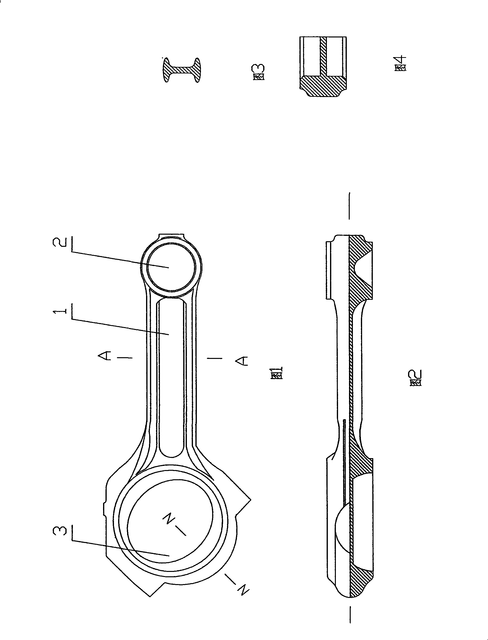
[0024] Technology of Connecting Rod for S195 Diesel Engine

[0025] Using the traditional die forging process to forge a connecting rod blank 1 with large and small heads through the forging die, and carry out shot blasting, flaw detection and phosphating treatment on the connecting rod blank; rough mill two planes, and process piston pin installation at the small head Hole, orifice chamfering 1×45°; take the center of the piston pin installation hole as the positioning reference involved in the subsequent processing procedure, cut along the elliptical minor axis of the overall blank big head pit, and form the connecting rod body blank and the connecting rod cover plate blank , and when forming the blank of the connecting rod body and the blank of the connecting rod cover plate, it is necessary to print the pairing marks, and then mill their cutting joint surfaces; merge the joint surfaces, and simultaneously drill the installation butt holes of the connecting rod body and the ...


PUM


Abstract

The invention relates to a process for manufacturing an internal-combustion engine connecting rod. The steps of the process are: forging, by a forging die, an integral blank of a connecting rod having a big end ad a small end, with the small end of the blank provided with opposite circular pits, the big end of the blank provided with opposite pits or a through hole, the edges of the pits or the hole on the big end being elliptical, the difference between a major axis and a minor axis being from 5 to 8mm, and the major axis superposing on the axis of the connecting rod or forming an included angle of 45 degrees with the axis of the connecting rod; subjecting the integral blank to blasting shot, flaw detection and phosphorization, then roughly milling two planes of the integral blank of the connecting rod, and machining an mounting hole for a piston pin on the small end; incising along the minor axis of the ellipse of the big end of the integral blank to form a blank of a connecting rod body and a blank of a connecting rod cover board, milling the incising junction surfaces; merging the junction surfaces, synchronously drilling the mounting jump-holes on the connecting rod body and the connecting rod cover board, and machining a crank mounting hole corresponding to the piston pin mounting hole on the big end; threading through the mount jump-holes on the connecting rod body, and machining a gap block position-limiting grooves in the connecting rod body and the connecting rod cover board; and removing burrs, and setting a positioning fixed bolt.

Description

technical field [0001] The invention relates to a manufacturing process of a connecting rod. Background technique [0002] The connecting rod is used in the internal combustion engine as the main part of the force transmission. Since the connecting rod is subjected to high periodic impact force, inertial force and bending force in the process of force transmission, the connecting rod must have a certain strength, Toughness and fatigue resistance, as well as high processing accuracy. At present, the main production processes of connecting rods are die casting process, die forging process, powder forging process, powder metallurgy process, powder hot extrusion-forging process, carbon fiber reinforcement technology, etc., because die forging has a geometric shape and dimensional accuracy close to the final product, and can improve its internal structure and obtain higher mechanical properties. Practice has proved that the fatigue strength and reliability of steel connecting rod...

Claims


Application Information

Patent Timeline
Patent Type & Authority Applications(China)
IPC IPC(8): F16C7/02
Inventor 蒋银海陈红伟
Owner 常州久弘金属材料有限公司
Learn More